The best electrical engineering projects for students are not the most impressive ones on a list. They are the ones built in the right order: a measured DC circuit, a timing circuit, an amplifier, a microcontroller that reads real signals, a complete system, and finally a project you design yourself. Each stage teaches one idea you can measure and explain.
Below are six builds in sequence, with what each teaches, the parts it needs, and the proof to keep.
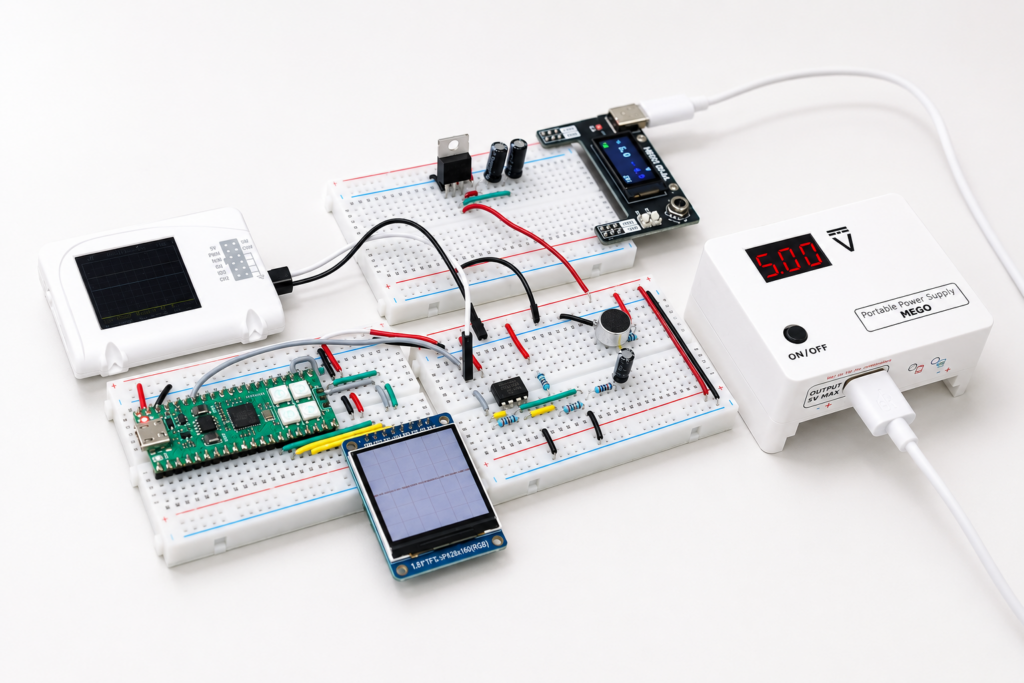
What makes a good electrical engineering project for a student?
If a project idea fails one of these four tests, skip it or change it.
- It teaches one core idea. A voltage divider teaches how voltage splits across resistance. A solar tracker with a battery charger, a motor driver, and Wi-Fi teaches you to copy a tutorial.
- You can predict the result. If you cannot write down an expected voltage, frequency, or behaviour before you build, you have nothing to compare against.
- You can measure it. A circuit that “works” but was never measured has not taught you much.
- It leaves evidence. A photo, a measured value beside the predicted one, and a note on what went wrong give you something to show an admissions reader or co-op interviewer.
The loop every project should follow: Predict → Build → Measure → Explain the difference.
When the measurement does not match the prediction, the explanation is the most valuable part of the project.
Which electrical engineering projects should students build first?
Each stage reuses a skill from the one before it, so skipping ahead usually means getting stuck on something the earlier project would have taught.
1. An LED indicator with a measured voltage divider (Ohm's law)
Wire an LED with a current-limiting resistor, then build a two-resistor voltage divider and measure its output.
- Parts and tools: a 5 V supply, a breadboard, a few red LEDs, 330 Ω and 10 kΩ resistors, and a multimeter.
- What it teaches: Ohm’s law, series resistance, and why calculated and measured values never match exactly.
- Evidence to keep: a table of predicted versus measured voltages, plus one sentence on the gap (resistor tolerance or the meter’s own loading of the circuit is usually the answer).
- Common trap: building the divider from very large resistors. The meter’s own resistance then pulls the reading low, and the “error” is the meter, not the circuit.
For more on both ideas, see EIM’s guides to Ohm’s law experiments and voltage divider applications.
2. A 555 blinking timer (RC circuits)
Use a 555 timer to charge and discharge a capacitor through a resistor over and over, so an LED blinks. Change the resistor and watch the blink rate change.
- Parts and tools: a 555 timer IC, a 10 µF capacitor, resistors between 1 kΩ and 100 kΩ, an LED, and an oscilloscope for the capture below. Because the 555 repeats the charge and discharge continuously, an oscilloscope shows the capacitor voltage rising and falling on every cycle, which a multimeter cannot.
- What it teaches: time constants (resistance multiplied by capacitance), and the idea that circuits behave differently over time.
- Evidence to keep: a capture of the capacitor voltage with two different resistor values.
- Common trap: inserting an electrolytic capacitor backward. The stripe marks the negative lead, which goes to the lower-voltage side.
3. An audio booster (op-amps)
Use an op-amp to amplify a weak signal and compare input with output. A phone playing a test tone through an audio cable is the easiest source. A microphone works too, but an electret microphone needs a bias resistor, and on a single supply the signal needs a coupling capacitor and a mid-supply reference, or the output sits against one rail.
- Parts and tools: a general-purpose op-amp such as the LM358, resistors to set the gain, coupling capacitors, and an oscilloscope to compare the two waveforms.
- What it teaches: gain, feedback, and why a real amplifier clips when you push it too far.
- Evidence to keep: the gain you calculated from the resistor values next to the gain you measured.
- Common trap: expecting the output to swing all the way to both supply rails. Many general-purpose op-amps, including the LM358, cannot reach the upper rail, so large signals flatten early.
Start with EIM’s op-amp basics guide if feedback is new to you.
4. A light meter (microcontroller and ADC)
Program a microcontroller to read an analog voltage through its analog-to-digital converter (ADC), then act on the number: light an LED, print a value, or trigger an output. A photoresistor in a voltage divider makes a simple light sensor.
- Parts and tools: a microcontroller board, a photoresistor, a 10 kΩ resistor, and a computer to program the board.
- What it teaches: how a continuous voltage becomes a stream of numbers, and what sampling means.
- Evidence to keep: the code, plus a log of how the reading changes as the light changes.
- Common trap: feeding a 5 V signal into the ADC pin of a 3.3 V microcontroller. Keep the input inside the board’s rated range, or the pin can be damaged.
For MicroPython on a microcontroller, see EIM’s embedded programming basics guide. For more builds at this stage, see Raspberry Pi Pico projects for beginners.
5. A live audio visualizer (complete signal chain)
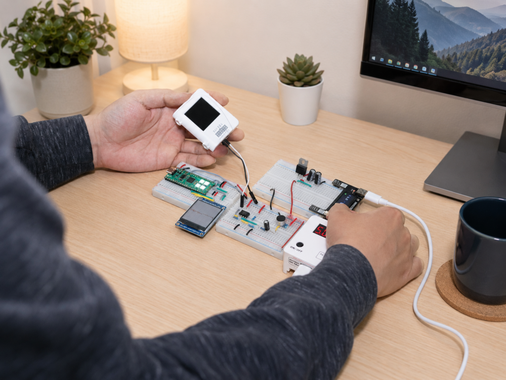
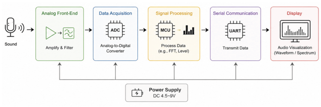
Connect everything: a microphone, an analog front end that conditions the signal, a microcontroller that samples it, and an output that shows the result.
- Parts and tools: a microphone, the op-amp stage from stage 3, the microcontroller board from stage 4, and a small display or RGB LEDs.
- What it teaches: system thinking, and debugging a system one stage at a time.
- Evidence to keep: a block diagram of the system and a short video of it running.
- Common trap: debugging the whole system at once. Check each stage’s output with a meter or oscilloscope before blaming the code.
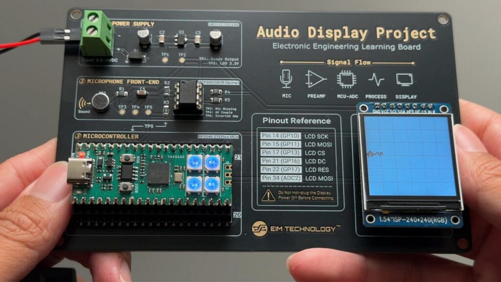
Image: https://eimtechnology.com/wp-content/uploads/2026/08/figure1-scaled.jpg | Alt text: Real-time audio visualizer running on the STEPICO RP2040 board with a microphone front end and ST7789 display | under the stage 5 heading
Image: https://eimtechnology.com/wp-content/uploads/2026/08/figure3.png | Alt text: Block diagram showing the signal path from sound through the analog frontend, ADC, RP2040 processing, and display | after the evidence bullet
EIM’s real-time audio visualizer project is an example of this stage. An analog microphone signal is sampled by the RP2040 microcontroller’s ADC and drawn as a live waveform on a small TFT display, with RGB LEDs showing signal strength.
6. A project you design yourself
Pick a small, real problem and design a circuit to solve it. If drawing your own schematic is new to you, start with how to read a schematic diagram. Write a one-paragraph specification first: what it must do, how you will test it, and what counts as success.
- Parts and tools: whatever your design needs, chosen and justified in your notes.
- What it teaches: engineering judgment. There is no tutorial, so every decision is yours.
- Evidence to keep: the specification, a schematic, test results against the specification, and what you would change in version two.
- Common trap: skipping the written specification, then calling whatever you built a success.
This project belongs at the top of a portfolio, because it shows how you think.
What is the full build order at a glance?
| Stage | Project | Core idea | Minimum equipment | Proof to keep |
|---|---|---|---|---|
| 1 | LED indicator and voltage divider | Ohm's law | Breadboard, resistors, multimeter | Predicted vs measured table |
| 2 | 555 blinking timer | RC time constants | 555 timer, capacitor, oscilloscope | Capacitor voltage capture |
| 3 | Audio booster | Gain and feedback | Op-amp, signal source, oscilloscope | Calculated vs measured gain |
| 4 | Light meter | ADC and sampling | Microcontroller board, photoresistor | Code and reading log |
| 5 | Live audio visualizer | System integration | Mic, op-amp stage, microcontroller, display | Block diagram and video |
| 6 | Your own design | Engineering judgment | Your choice, justified | Spec, schematic, test results |
Which projects suit high school, first-year, and senior students?
- High school students: finish stages 1 to 3 and attempt stage 4. Those builds cover the tools a first-year electronics lab assumes you can pick up quickly: a breadboard, a multimeter, and a schematic. For why building early helps, see EIM’s article Build Before You Study.
- First-year university students: work through stages 4 and 5 while your courses cover the theory behind the first three.
- Senior and capstone students: you are at stage 6 with a team, a budget, and an advisor. The earlier habits still matter most: a written specification, measured results, and an honest record of what failed.
Lab-On-The-Go Electronics Tool Kit
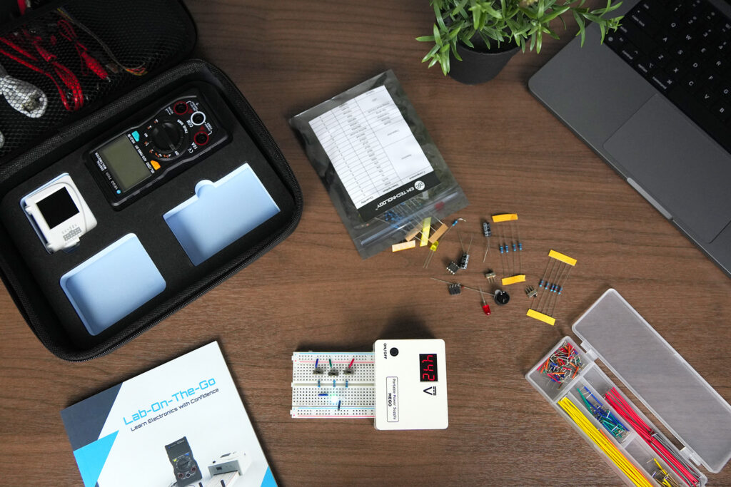
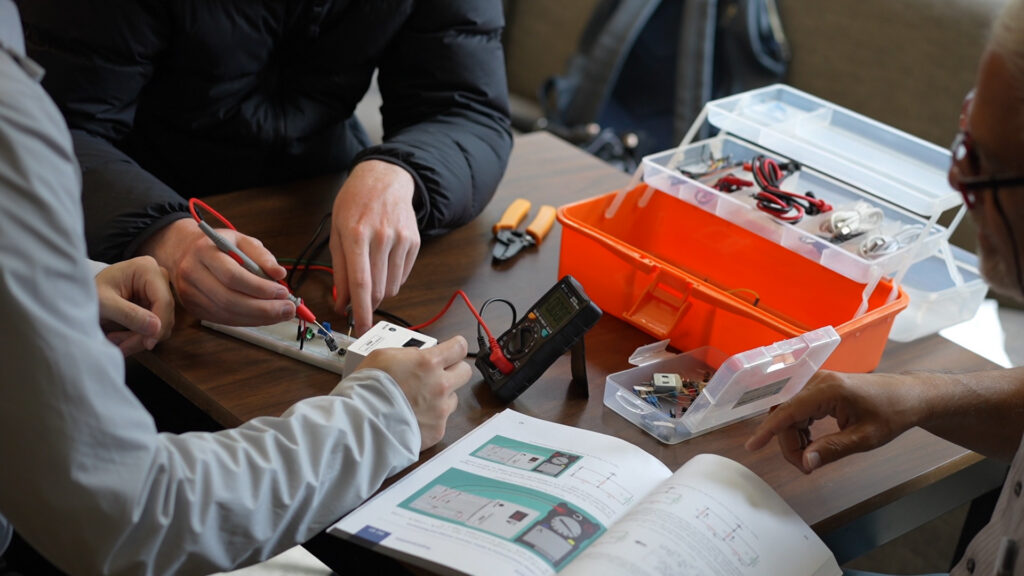
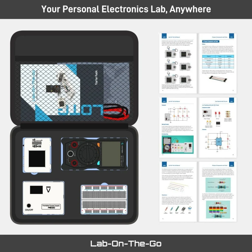
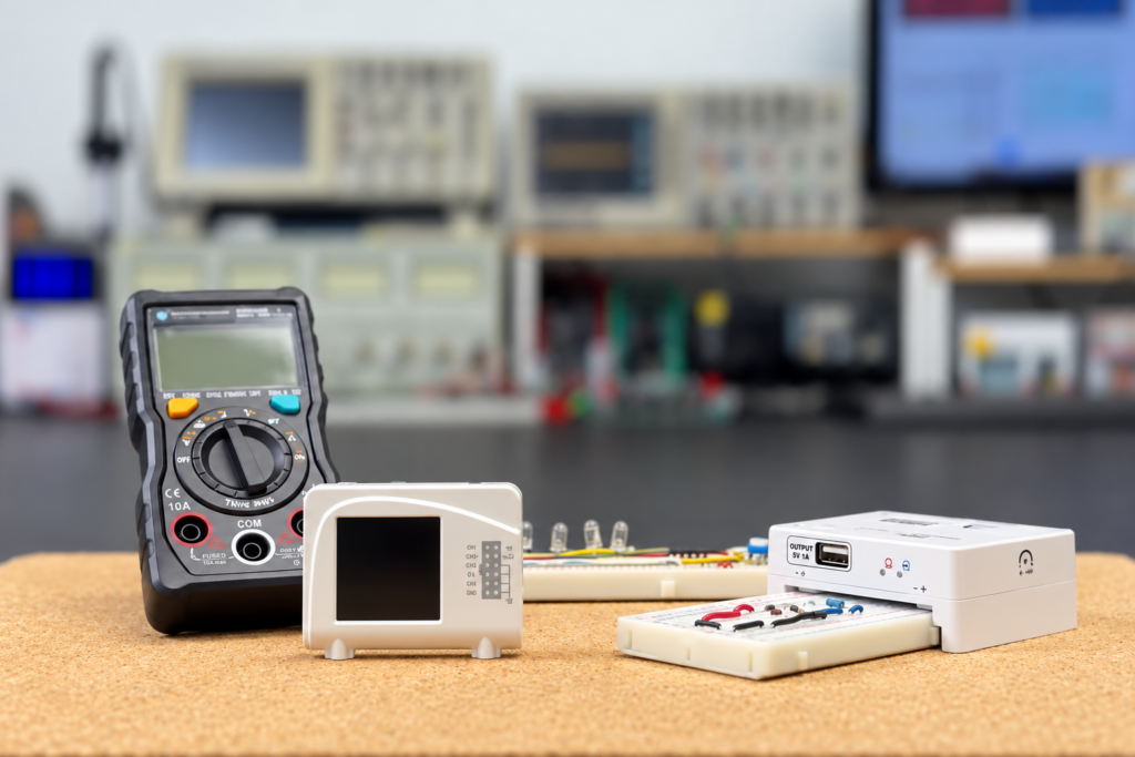
The measuring step is where many learners get stuck, because it depends on instruments that are not always accessible outside a lab. A portable kit such as the Lab-On-The-Go puts a rechargeable power supply, a digital multimeter, and an oscilloscope with a function generator in one case, so a student can capture that unexpected waveform at their own desk and work through the loop at their own pace
What equipment do students need for electronics projects?
First DC circuits need only a breadboard, components, and a multimeter. From timing circuits onward, an oscilloscope stops being a luxury. EIM’s Lab-on-the-Go puts an oscilloscope, a waveform generator, a power supply, and a multimeter in one portable kit.
| Setup | Good for | Limitation |
|---|---|---|
| Loose components and a multimeter | First DC circuits | No way to see changing signals |
| Microcontroller starter kit | Microcontroller projects | Often skips the analog stages |
| Structured electronics kit with a lab guide | Analog and microcontroller stages, in a set order | Costs more up front than loose parts |
| Kit plus portable measurement instruments | All six stages with real measurement | Highest starting cost |
For a fuller list, see how to build an electronics lab and best oscilloscope for beginners.
How do you turn a project into resume or portfolio evidence?
For every build, keep a one-line problem statement, a photo or short video, one measurement compared with your prediction, and one failure with its fix. Interviewers often ask about failures, because they show how you debug.
For the full write-up method, see EIM’s guide on how to make an engineering portfolio as a student.
What mistakes do students make with electrical engineering projects?
- Starting with a capstone-sized idea. A first project with five subsystems usually ends half-built.
- Copying a tutorial without predicting anything. If you never wrote down what you expected, you cannot say what you learned.
- Skipping measurement. “The LED lit up” is not a result. “The LED current was close to what I calculated” is.
- Working with mains voltage too early. Wall-powered projects can injure you. Stay with batteries and low-voltage supplies until you have supervision and training.
- Not recording failures. The project that did not work the first time is often the best story in your portfolio.
Where does the Fundamental EE Starter fit?
Disclosure: this article is from EIM Technology, which makes the Fundamental EE Starter (FE11).
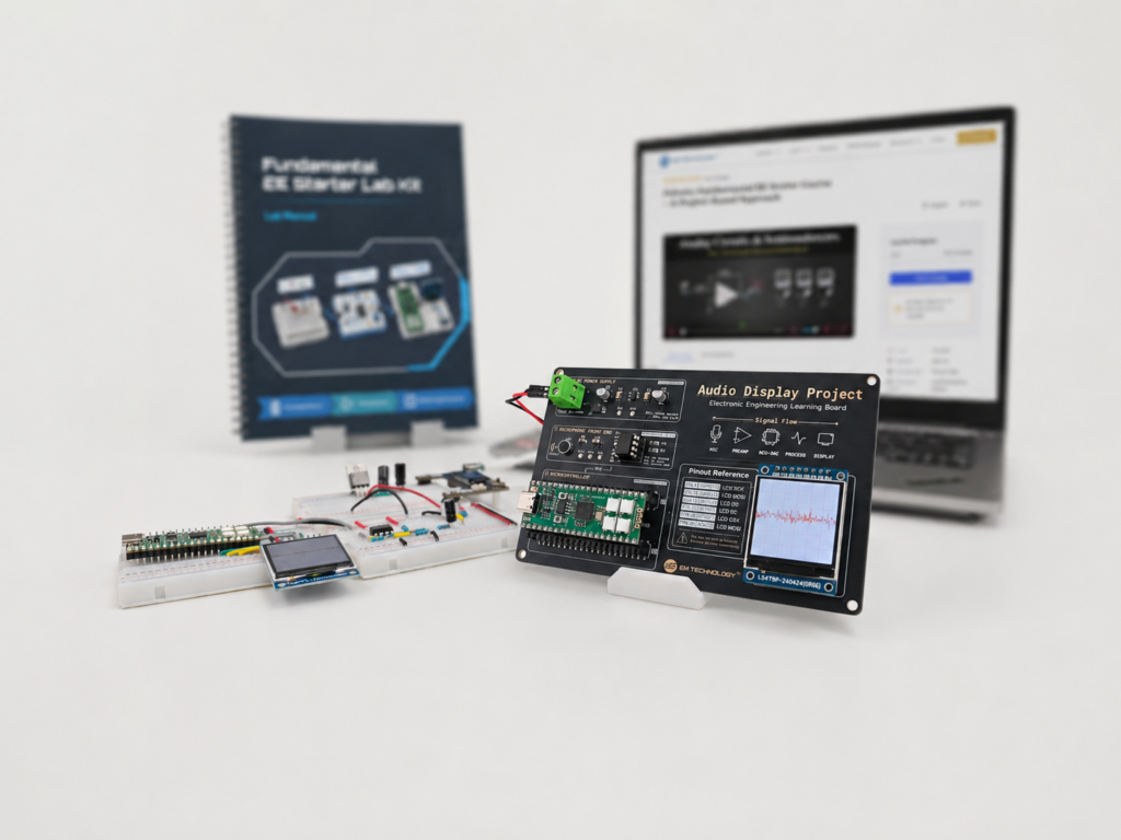
This article covers the core idea of each stage. If you want to go further with real hardware, the Fundamental EE Starter (FE11) connects circuits, analog design, and microcontrollers in one structured kit. Its embedded section uses the RP2040 microcontroller with MicroPython, and EIM’s audio visualizer in stage 5 is built with it. Learners can optionally submit lab results for feedback from the EIM engineering team.
Why choose a kit instead of loose parts?
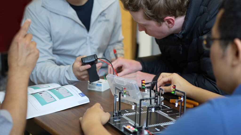
- A systematic curriculum. FE11 comes with a printed lab manual and structured online learning materials, so the order is planned for you.
- Dedicated hardware that works together. FE11 includes two sets: through-hole components and ICs for plug-and-play breadboard learning, and a fully soldered surface-mount PCB for more durable applications once you understand the core concepts.
- A path to real applications. The same platform runs an audio oscilloscope, a spectrum analyzer, an interactive particle sandbox, and a guided breathing trainer.
For the learning path behind this sequence, see How to Learn Electronics and Computer Engineering.
Frequently asked questions
What is a good first electrical engineering project for a student?
An LED with a current-limiting resistor, followed by a voltage divider you measure with a multimeter. It is cheap, safe, and teaches Ohm’s law with a result you can check.
Do I need an oscilloscope for student electronics projects?
Not for your first DC circuits. From timing circuits onward, an oscilloscope shows how a signal changes over time, which a multimeter cannot.
Are Arduino projects good electrical engineering projects?
They are good microcontroller projects. Many Arduino projects stop at reading a sensor value with analogRead or switching a pin with digitalWrite. Electrical engineering starts with the circuit in front of that pin: the divider, filter, or amplifier that makes the signal worth reading. Pair microcontroller projects with circuit and amplifier projects.
How many projects should a student have before applying to engineering programs?
There is no required number. Two or three projects you can explain in depth, each with measurements and a record of what failed, are a strong base. A long list you cannot discuss is weaker.
What electrical engineering projects look good on a resume?
Projects you designed yourself, with a written specification and measured test results. A complete signal chain or an original design shows more than a kit assembled by following steps.

EIM TECHNOLOGY
Founder & Engineering Education Innovator
Daniel Cao is the Founder of EIM Technology and holds a Master of Applied Science in Engineering. With experience in engineering research, product development, PCB design, and technical education, he is the author of several books on electronics engineering. His work focuses on developing practical learning systems that integrate engineering hardware, lab instruments, curriculum, and project-based learning. Through EIM Technology, Daniel aims to make electronics and computer engineering more accessible and engaging, helping students build real experience in designing, measuring, testing, and troubleshooting electronic systems.