The best Raspberry Pi Pico projects for beginners teach the circuit around the board, not just the code. Start with an LED you size yourself, then a button, an analog sensor on the ADC, a PWM dimmer, and finally a live audio visualizer and spectrum analyzer. Each project adds one new RP2040 feature or circuit idea to the last.
A project that only plugs in a sensor module teaches little about the circuit. The six projects below each add one new idea and name the circuit you build in front of the pin. Projects 1 to 4 are general warm-ups that work on any Pico; projects 5 and 6 match builds EIM has documented on RP2040 hardware
What makes the Raspberry Pi Pico good for beginner projects?
The original Raspberry Pi Pico is built on the RP2040 microcontroller. It has a dual-core processor running at up to 133 MHz, 264 kB of SRAM, 2 MB of flash, 26 multi-function GPIO pins, three 12-bit ADC inputs, 16 PWM channels, and eight Programmable I/O (PIO) state machines. It runs MicroPython, which lets you test hardware one line at a time.
For a beginner, two things matter most: it has real analog inputs, so you can read a changing voltage directly, and it runs at 3.3 V, so 5 V signals must never go straight into its pins.
The newer Pico 2 uses the RP2350 chip. The projects below also work on the wireless Pico W and Pico 2 W without using Wi-Fi, and most beginner MicroPython code carries over between them. Check the pinout and firmware for your exact board, since the onboard LED is wired differently on the wireless versions.
The pattern every project below follows: Circuit → Code → Measure → Change one thing → Explain what happened.
Which Raspberry Pi Pico projects should beginners build first?
1. An LED blink with a resistor you calculate
Connect an LED and a current-limiting resistor to a GPIO pin, then make it blink.
					from machine import Pin
import time

led = Pin(15, Pin.OUT)

while True:
    led.toggle()
    time.sleep(0.5)
- Circuit: GPIO 15 → resistor → LED anode, LED cathode → GND. A 330 Ω resistor is a safe starting value at 3.3 V; the exact current depends on your LED’s forward voltage, which is why you measure it.
- RP2040 feature: digital output.
- What it teaches: Ohm’s law in a working circuit, and why the resistor is not optional.
- Try changing: the resistor value. Measure the LED current with a multimeter each time and compare it with your calculation.
2. A button that does not misfire
Read a push button and toggle the LED each time it is pressed.
					from machine import Pin
import time

led = Pin(15, Pin.OUT)
button = Pin(14, Pin.IN, Pin.PULL_UP)

while True:
    if button.value() == 0:      # 0 means pressed (pull-up)
        led.toggle()
        time.sleep(0.05)         # let the contacts stop bouncing
        while button.value() == 0:
            pass                 # wait for release
        time.sleep(0.05)
Circuit: one side of the button to a GPIO pin, the other to GND, with the pin’s internal pull-up enabled (Pin(14, Pin.IN, Pin.PULL_UP)).
RP2040 feature: digital input with internal pull-up.
What it teaches: why an unconnected input “floats” and reads random values, and why a mechanical button bounces. Add a short delay after each press and watch the misfires disappear.
Try changing: remove the pull-up, print the pin value in a loop, and touch the wire with your finger. Your body picks up electrical noise from nearby wiring, and the reading flips. That is a floating input.
3. A light meter on the ADC
Build a voltage divider from a photoresistor and a fixed resistor, connect the midpoint to an ADC pin, and print the voltage.
					from machine import ADC
import time

sensor = ADC(26)

while True:
    raw = sensor.read_u16()
    volts = raw * 3.3 / 65535
    print(round(volts, 2))
    time.sleep(0.2)
Circuit: 3.3 V → photoresistor → ADC pin (GP26) → 10 kΩ resistor → GND.
RP2040 feature: the ADC.
What it teaches: how a voltage divider turns a changing resistance into a changing voltage, and how a voltage becomes a number.
Worth knowing: read_u16() returns a value from 0 to 65535, but the RP2040’s ADC is 12-bit. MicroPython scales every port’s ADC reading to 16 bits so the same code works on different boards. The lowest bits carry no extra information.
4. A PWM dimmer
Use pulse-width modulation (PWM) to dim the LED from project 1, then control the brightness with the light meter from project 3.
					from machine import Pin, PWM, ADC
import time

led = PWM(Pin(15))
led.freq(1000)
sensor = ADC(26)

while True:
    led.duty_u16(sensor.read_u16())   # more light, brighter LED
Circuit: the LED and 330 Ω resistor from project 1 on GPIO 15, plus the photoresistor divider from project 3 on GP26.
RP2040 feature: PWM.
What it teaches: that a “dimmed” LED is really switching fully on and off very fast, and that the average voltage depends on the duty cycle.
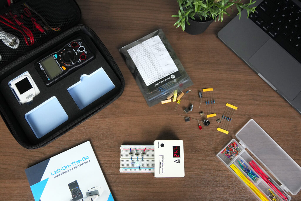
Try changing: if you have an oscilloscope, such as the one in EIM’s Lab-on-the-Go, watch the PWM pin. The square wave changes width as the brightness changes.
Projects 5 and 6 are a step up. They combine an analog front end, a display bus, and much more code, so treat them as capstones and build them in stages.
5. Capstone: a real-time audio visualizer
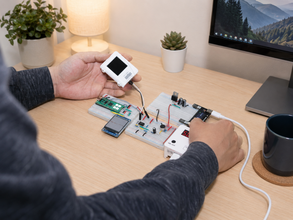
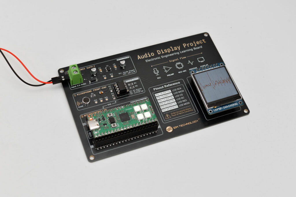
Amplify a microphone signal, sample it with the ADC, and draw the waveform on a small display. Before adding the display, print the raw ADC readings from the amplified microphone and watch them swing around the middle of the range when you speak. That confirms the analog stage works before you debug any display code. If you have never used a display, get it to show a single number over SPI before you try to draw a waveform.
					from machine import ADC
import time

mic = ADC(28)

while True:
    print(mic.read_u16())   # sits near 32768 when the bias is at mid-supply
    time.sleep(0.01)
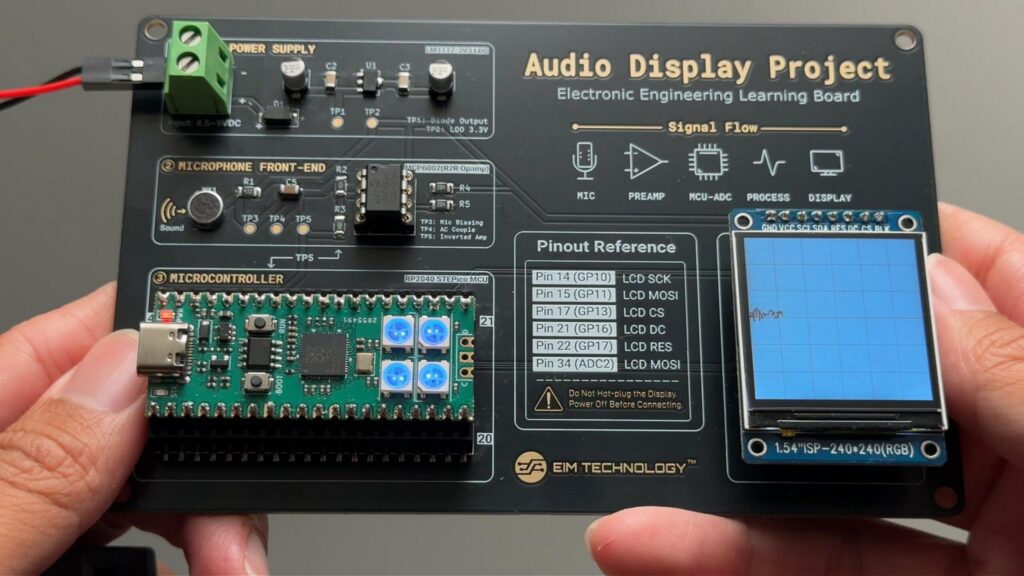
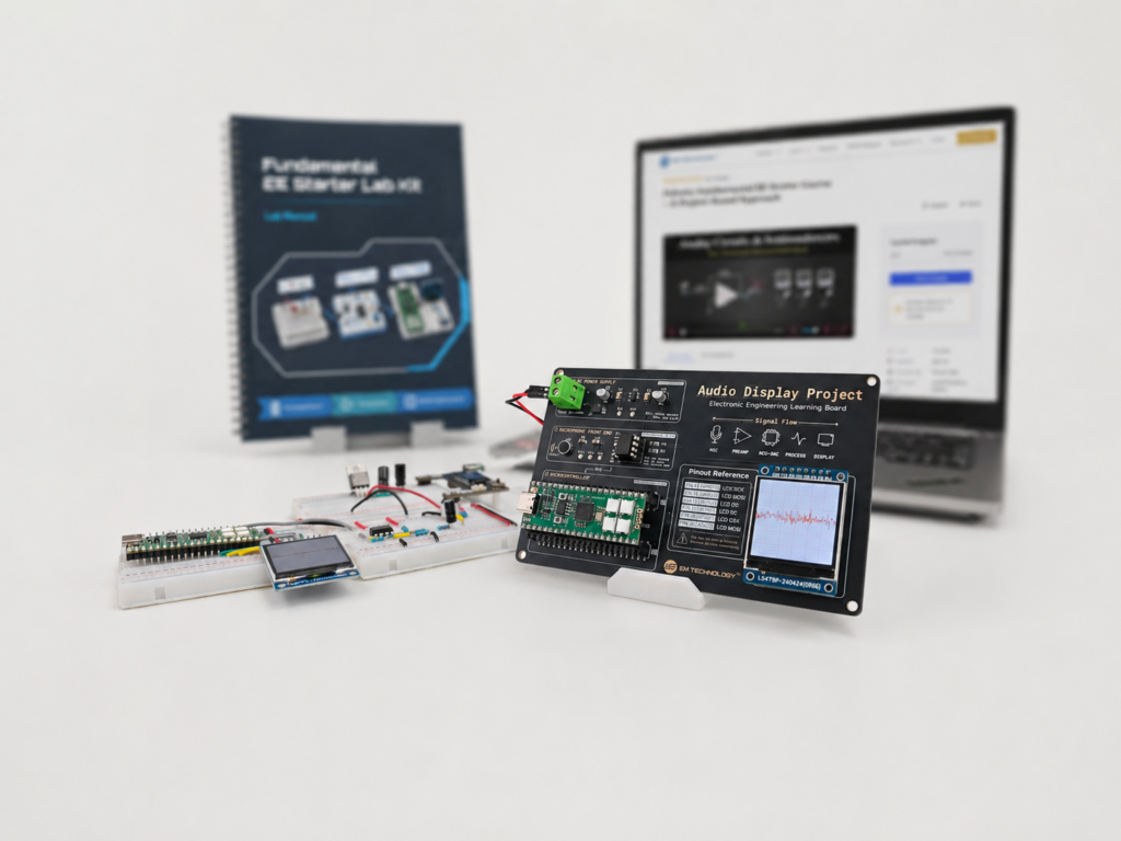
EIM’s real-time audio visualizer project is a documented version of this build, and EIM’s FE11 project documentation includes the full MicroPython program and the ST7789 display driver. An analog microphone signal feeds the RP2040’s ADC, a MicroPython program converts the samples into a waveform on a 240 × 240 ST7789 TFT display, and four WS2812 RGB LEDs show the approximate signal strength.
- Circuit: a microphone with an amplifier and a biasing stage (see how to read a schematic diagram if the front-end drawing is new to you) that centres the audio signal at about half of the 3.3 V supply, so it stays inside the ADC’s input range. Keep the analog wiring short; long jumpers pick up noise.
- RP2040 feature: the ADC, plus SPI to drive the display.
- What it teaches: how a complete signal chain works, from sound pressure to voltage to numbers to pixels.
- Try changing: one input at a time. Compare a quiet room, normal speech, and a hand clap, and explain what each trace shows.
6. Capstone: a spectrum analyzer
Take the audio samples from project 5 and run a fast Fourier transform (FFT) to show how much of each frequency is in the sound.
- Circuit: the same front end and display as project 5.
- RP2040 feature: processing power, since the FFT runs on the microcontroller itself. Standard MicroPython firmware has no built-in FFT, so you either write a small FFT function or use firmware that includes the ulab library.
- What it teaches: the difference between a signal in time (a waveform) and in frequency (a spectrum).
- Try changing: play a single tone, then speech. A tone shows one strong bar; speech spreads across many.
EIM’s Project Showcase includes an RP2040 audio display system that shows FFT visualization on an ST7789 display, programmed in MicroPython.
What does each Pico project teach?
| # | Project | RP2040 feature | Circuit you build | Core lesson |
|---|---|---|---|---|
| 1 | LED blink | Digital output | LED and current-limiting resistor | Ohm's law |
| 2 | Button toggle | Digital input, pull-up | Button to ground | Floating inputs and bounce |
| 3 | Light meter | ADC | Photoresistor voltage divider | Voltage to number |
| 4 | PWM dimmer | PWM | LED circuit plus photoresistor divider | Duty cycle |
| 5 | Audio visualizer | ADC and SPI | Microphone amplifier and bias | Complete signal chain |
| 6 | Spectrum analyzer | Processing (FFT) | Same as project 5 | Time vs frequency |
What mistakes do beginners make with Raspberry Pi Pico projects?
- Connecting a 5 V signal to a GPIO or ADC pin. The RP2040 runs at 3.3 V. Use a voltage divider or a level shifter for 5 V signals.
- Leaving out the LED resistor. The LED and the pin both depend on it.
- Forgetting a shared ground. Every module in the circuit must connect to the Pico’s GND.
- Trusting read_u16() as 16-bit data. The ADC is 12-bit; the value is scaled.
- Leaving inputs floating. Use the internal pull-up or pull-down, or an external resistor.
- Copying a pin number from a tutorial for a different board. The onboard LED is wired differently on the wireless Pico W and Pico 2 W, and pin layouts differ on other RP2040 or RP2350 boards. Check the pinout for yours.
Where does the Fundamental EE Starter fit?
Disclosure: this article is from EIM Technology, which makes the Fundamental EE Starter (FE11).
The Fundamental EE Starter (FE11) runs on EIM’s STEPICO board, which is built on the RP2040 and is pin-compatible with a standard Raspberry Pi Pico: every exposed pin is identical. STEPICO uses USB-C instead of micro-USB and adds four on-board full-colour LEDs driven by the RP2040’s internal GP23, a pin the standard Pico does not bring out. The code in this article runs on it as written.
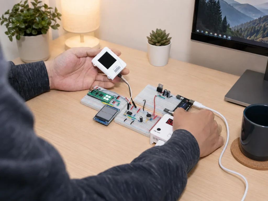
If you already own a Pico, projects 1 to 4 need only a breadboard and a few parts; projects 5 and 6 add a microphone amplifier and a small SPI display. If you want a planned path instead of sourcing parts yourself, FE11 brings the circuits, the RP2040 hardware, and a structured curriculum together in one kit, and you can optionally submit lab results for feedback from the EIM engineering team.
Why choose a kit instead of loose parts?
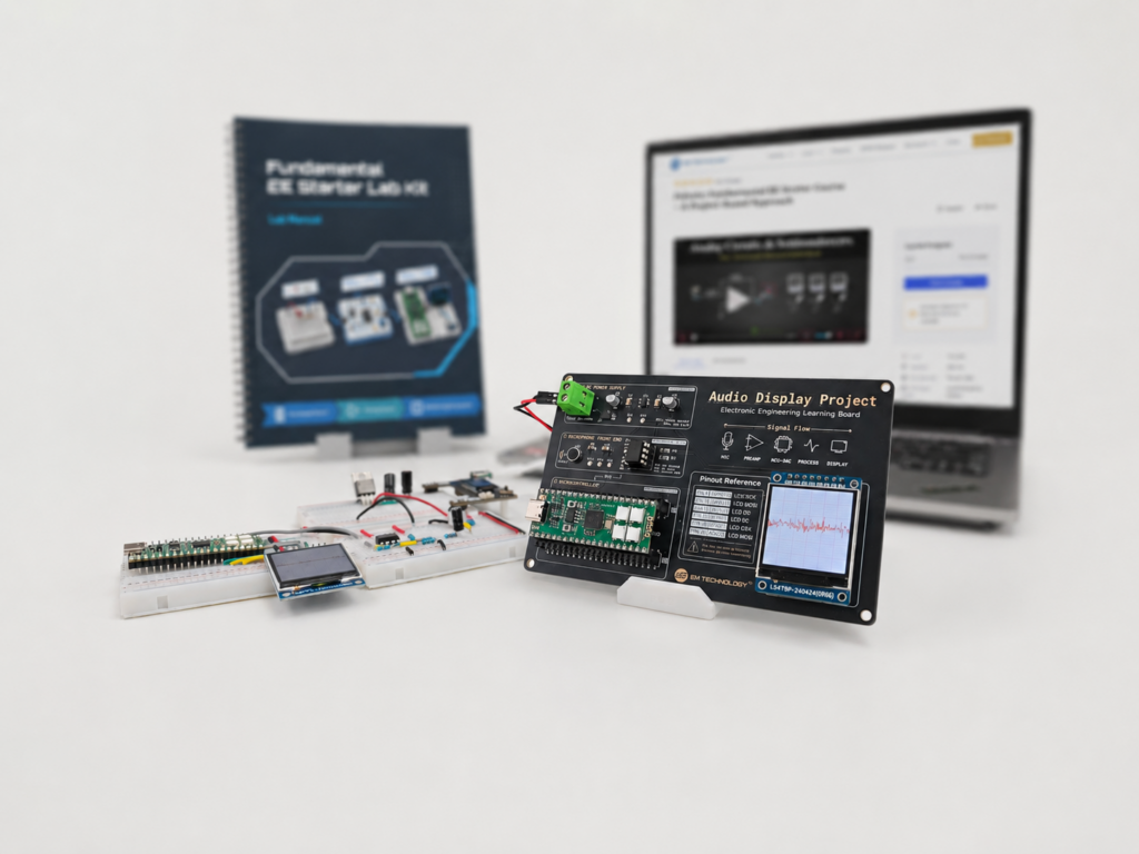
- A systematic curriculum. FE11 comes with a printed lab manual and structured online learning materials, so the order is planned for you.
- Dedicated hardware that works together. FE11 includes two sets: through-hole components and ICs for plug-and-play breadboard learning, and a fully soldered surface-mount PCB for more durable applications once you understand the core concepts.
- A path to real applications. The same platform runs an audio oscilloscope, a spectrum analyzer, an interactive particle sandbox, and a guided breathing trainer.
Buy the Fundamental EE Starter (FE11)
For a build order that starts before the microcontroller, see electrical engineering projects for students. For MicroPython fundamentals, see EIM’s embedded programming basics guide. For the wider learning path, see How to Learn Electronics and Computer Engineering.
Fundamental EE Starter, FE11
For learners who want a structured way to build that habit, the Fundamental EE Starter kit (FE11) follows one connected path through circuits, analog design, microcontrollers, PCBs, and guided projects, with an online learning platform alongside the hardware. AI can explain each concept along the way, while the kit keeps the learning grounded in real circuits.
Frequently asked questions
Can I damage a Pico with these projects?
Yes, mainly by putting more than 3.3 V on a pin or by shorting an output pin straight to ground or to the supply. A series resistor on every LED, and a wiring check before you plug in USB, prevent most damage.
Should I use MicroPython or C/C++ on the Pico?
Start with MicroPython, which lets you test hardware line by line. Move to C/C++ when you need tighter timing or more speed.
How many analog inputs does the Raspberry Pi Pico have?
The original Pico exposes three 12-bit ADC inputs on its GPIO pins. The RP2040 also has an internal temperature sensor connected to the ADC.
What is the difference between a Raspberry Pi Pico and a Raspberry Pi?
A Raspberry Pi is a small computer that runs an operating system. A Pico is a microcontroller board that runs one program directly on the hardware, which makes it better suited to reading sensors and controlling circuits in real time.
Do Pico projects work on other RP2040 boards?
Usually, if you adjust the pin numbers. The code depends on the RP2040 chip, while the pin layout depends on the board. Boards that keep the Pico’s pinout, such as EIM’s STEPICO, run the code in this article without pin changes.

EIM TECHNOLOGY
Founder & Engineering Education Innovator
Daniel Cao is the Founder of EIM Technology and holds a Master of Applied Science in Engineering. With experience in engineering research, product development, PCB design, and technical education, he is the author of several books on electronics engineering. His work focuses on developing practical learning systems that integrate engineering hardware, lab instruments, curriculum, and project-based learning. Through EIM Technology, Daniel aims to make electronics and computer engineering more accessible and engaging, helping students build real experience in designing, measuring, testing, and troubleshooting electronic systems.