A hands-on preparation plan for students who want to turn university theory into real measurements, debugging experience, and a project they can confidently demonstrate.
The short answer: To prepare for a first electronics or computer engineering co-op or internship in six weeks, focus on hands-on skills you can show. Practice with a multimeter, oscilloscope, signal generator, and power supply; debug breadboard circuits; connect a microcontroller to real signals; and document one integrated project with measurements, code, and a short demo.
Your first co-op is an important opportunity to enter an engineering workplace, but the application window often arrives before you have completed many advanced electronics or computer engineering courses. You might know Ohm’s law, op-amp equations, or basic programming and still feel uncertain when someone hands you a breadboard, a datasheet, and an oscilloscope. That gap is one reason good electronics students often struggle with real hardware at first.
If you have only six weeks, there is little value in pretending you can become an experienced engineer overnight. You cannot rewrite your GPA or complete several semesters of coursework in that time. What you can change is your ability to build a circuit, measure what is happening, find a fault, and explain the results. For an introductory hardware testing, electronics validation, or embedded systems co-op, that is a much more realistic starting point.
The goal is not six weeks of impressive-looking projects. It is six weeks of real engineering practice, with evidence of what you personally built, tested, and understood.
How do you turn circuit theory into something you can measure?
Many engineering students first encounter circuit theory as equations, diagrams, and assignments. Those ideas become much more meaningful when you can see the behavior on a real instrument. A resistor-divider calculation becomes a voltage you measure with a multimeter. An RC filter becomes an input and output waveform you compare on an oscilloscope. A frequency-response equation becomes a curve you can investigate by changing the signal-generator frequency.
The most valuable discoveries are often the details that textbook exercises simplify. Where should the ground reference be connected? Why does a supply show ripple or noise? Why does an op-amp output saturate? What do the datasheet’s supply limits, pin descriptions, and typical application circuits actually mean? Why does the measured response differ from your calculation? These are not distractions from engineering theory; they are the reason the theory matters.
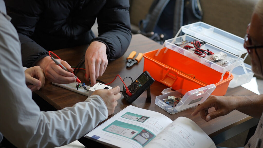
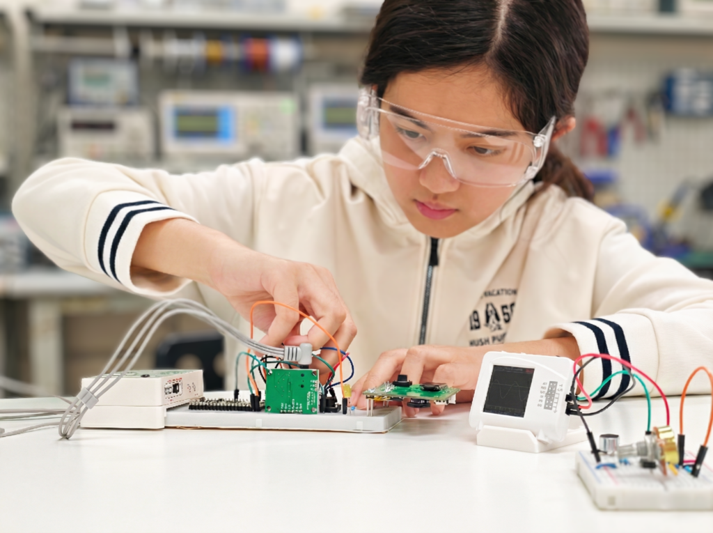
Spend time using the instruments rather than simply completing instructions. Measure the same circuit under different conditions. Change one component at a time. Compare expected and observed results. Make a deliberate wiring mistake on a safe, low-voltage practice circuit, then use measurements to locate it. When you can explain the discrepancy, you are learning the habits behind real troubleshooting.
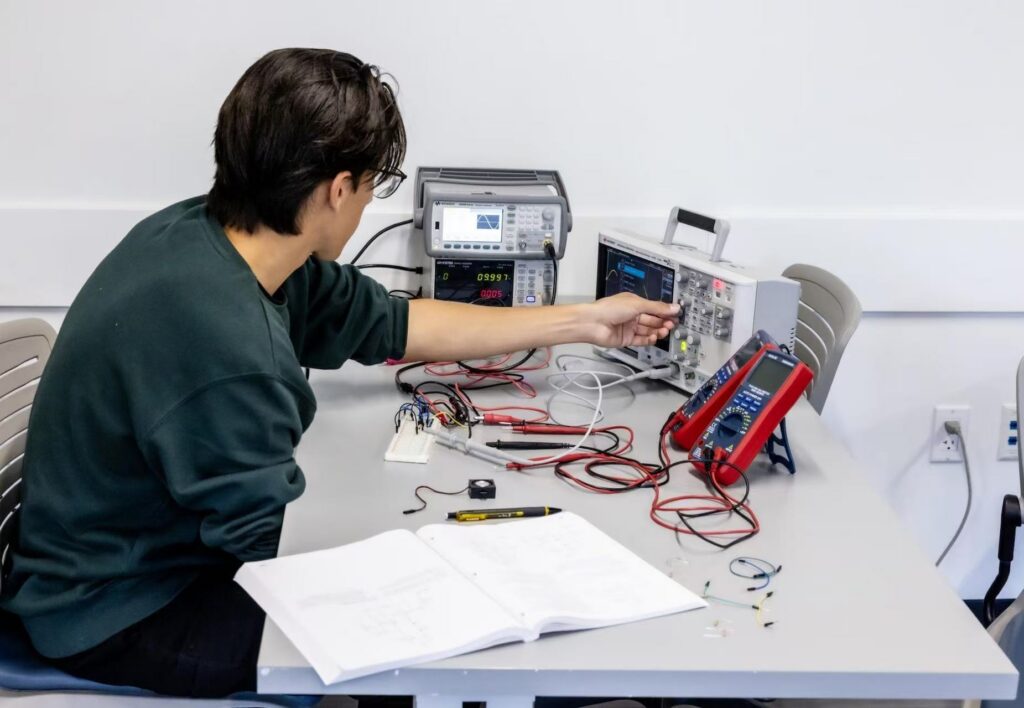
What should a six-week co-op preparation plan include?
This schedule is designed for a student who can dedicate roughly 8–10 focused hours per week alongside university classes. It is an illustrative learning plan, not a guaranteed completion schedule. The important rule is to keep one coherent record of your work instead of starting unrelated projects every few days.
| Time | What to practice | What to keep |
|---|---|---|
| Week 1 | Multimeter, power supply, oscilloscope, and signal generator; breadboard circuits, ground reference, and safe measurement habits. | Circuit photos, voltage readings, and first waveform captures. |
| Week 2 | RC filters, frequency response, supply ripple and noise, interpreting datasheets, and comparing measurements with theory. | Frequency-response observations and a short measurement log. |
| Week 3 | Op-amp and signal-conditioning experiments: gain, clipping, bandwidth, and troubleshooting incorrect behavior. | Test results and one documented fault-and-fix example. |
| Week 4 | Microcontroller basics: GPIO, ADC and PWM, reading sensors or signals, and connecting code to physical behavior. | Working source code, wiring diagram, and demonstration clip. |
| Week 5 | Communication interfaces such as UART, SPI, or I²C; verify signals and combine circuit and firmware. | Protocol observations, block diagram, and debug notes. |
| Week 6 | Finish one integrated project; test, refine, document, and present the complete engineering process. | Project photos, measurements, code, diagram, and a short demo video. |
For the final project, keep the scope manageable. For example, condition a simple sensor or audio signal with an analog circuit, measure it with an oscilloscope, read it using a microcontroller, and display or transmit the result. A simpler filter-and-measurement project is also valid if you can explain it deeply. Your project should tell a coherent story: what you intended to build, what the circuit did, what went wrong, and how you verified the correction.
The most useful outcome is not a polished gadget. It is being able to point to a schematic, a waveform, a datasheet, a piece of code, and a test result, and explain how they relate to one another.
What equipment do you need to practice outside university labs?
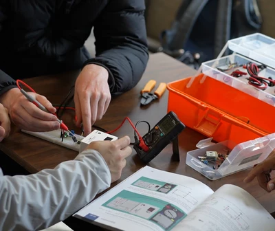
A common obstacle is having tutorials but no instruments, or owning a development board without knowing how to investigate the signals around it. Collecting disconnected parts and online resources can consume the few weeks you hoped to spend practicing. Scheduled lab sessions help, and it is worth learning how to get more from university electronics labs, but focused preparation often needs more repetition than scheduled sessions allow.
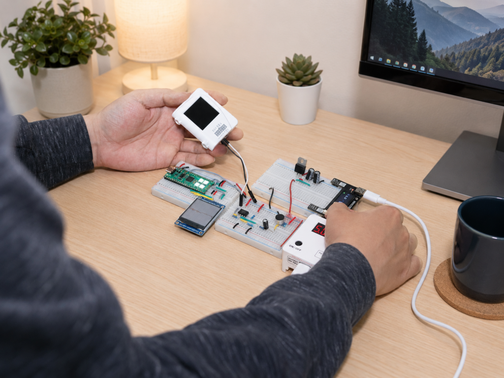
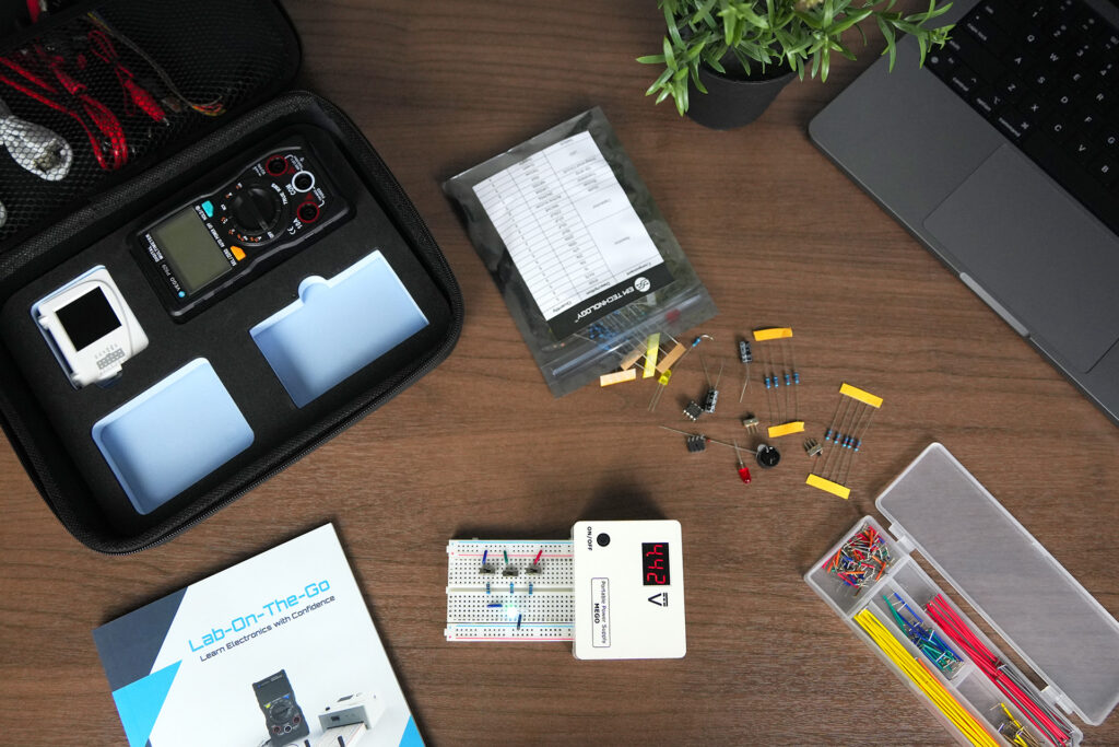
EIM Technology’s Lab on the Go brings together portable instruments for introductory electronics measurement: an oscilloscope, signal generator, power supply, and digital multimeter. It gives students a practical way to repeat measurements, inspect waveforms, and debug suitable low-voltage circuits outside scheduled university laboratory sessions. If you are still deciding which instrument features matter at this stage, see the guide to the best oscilloscope for beginners.
FE11 Fundamental EE Starter provides the complementary structure: physical electronics hardware, instructional materials, and a sequence of experiments that connects circuit fundamentals with practical system-building. Used together, FE11 helps answer “What should I build and understand next?” while Lab on the Go helps answer “What is my circuit actually doing?”
This is a focused starting point for students preparing for their first electronics or computer engineering hardware-related co-op. It is not intended to replace advanced university labs or turn a beginner into a professional engineer in six weeks. The value is repeatable hands-on practice and a credible foundation for the next opportunity.
If you want to go further after the fundamentals, EIM’s planned Digital & Embedded (FE22) stage is intended to extend into microcontrollers, FPGA logic, communication protocols, and hardware-software collaboration. The planned EE Systems (FE33) stage goes further into analog and integrated system design. These are optional next steps for deeper preparation, not requirements for a first co-op.
Fundamental EE Starter, FE11
For learners who want a structured way to build that habit, the Fundamental EE Starter kit (FE11) follows one connected path through circuits, analog design, microcontrollers, PCBs, and guided projects, with an online learning platform alongside the hardware. AI can explain each concept along the way, while the kit keeps the learning grounded in real circuits.
How do you show co-op employers what you can do?
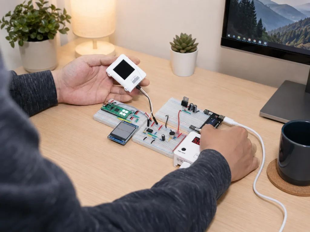
The strongest advantage of hands-on work is that you now have something real to show. Photograph your circuit, save your oscilloscope captures, record a short demonstration, and write down the problem you solved. A simple project becomes much more credible when you can show the measurements behind it.
You can also share the process publicly. Post a short update on LinkedIn after a meaningful experiment: a photo of your setup, the concept you tested, what surprised you, and one thing you learned. When you complete a project, share a concise demo and link to the code or documentation if appropriate. These posts do not need elaborate production or paid promotion. Over time, they create a visible trail of your technical curiosity and progress.
Do not claim that every post will attract recruiters or guarantee an interview. The point is simpler: when someone asks what you have worked on, you can show real hardware, actual measurements, and a sequence of problems you learned to solve. That is more convincing than a vague statement that you are “passionate about electronics
Frequently asked questions
Can ECE and EE students prepare for a first hardware co-op in six weeks?
You can build a realistic starting point in six weeks, but not the experience of several semesters. Focus on building circuits, measuring them, finding faults, and explaining the results.
How many hours per week does this six-week plan take?
The plan assumes roughly 8–10 focused hours per week alongside university classes. It is an illustrative schedule, not a guaranteed completion timeline.
What project should you build before your first co-op?
Choose one manageable, integrated project rather than several unrelated ones. For example, condition a sensor or audio signal with an analog circuit, measure it with an oscilloscope, read it with a microcontroller, and display or transmit the result. A simpler filter-and-measurement project is also valid if you can explain it in depth.
Do you need your own instruments to prepare for a hardware co-op?
Scheduled university lab sessions are useful, while portable instruments let you repeat measurements and debug suitable low-voltage circuits on your own schedule. The goal is enough repetition with a multimeter, oscilloscope, signal generator, and power supply to use them with confidence.
What should you show employers from your preparation?
Show evidence of the engineering process: circuit photos, oscilloscope captures, measurement logs, source code, a wiring or block diagram, a documented fault-and-fix example, and a short demo video. Be ready to explain how the schematic, waveform, datasheet, code, and test results relate to one another.
Where should you start?
Your first co-op is a beginning, not the finish line. Six weeks will not teach you everything, but they can change how you approach the next course, laboratory, technical conversation, and engineering project. Once you have measured real signals, debugged real circuits, and connected software to physical hardware, much of what you learned in class starts to look different. If you are working through this plan on your own, it also helps to understand whether you can learn electronics engineering on your own.
Start with a circuit. Measure it. Debug it. Build a small system. Share what you learned.
Explore EIM Technology’s Lab on the Go and FE11 Fundamental EE Starter as a practical starting combination for your first hardware-focused co-op preparation.

EIM TECHNOLOGY
Founder & Engineering Education Innovator
Daniel Cao is the Founder of EIM Technology and holds a Master of Applied Science in Engineering. With experience in engineering research, product development, PCB design, and technical education, he is the author of several books on electronics engineering. His work focuses on developing practical learning systems that integrate engineering hardware, lab instruments, curriculum, and project-based learning. Through EIM Technology, Daniel aims to make electronics and computer engineering more accessible and engaging, helping students build real experience in designing, measuring, testing, and troubleshooting electronic systems.