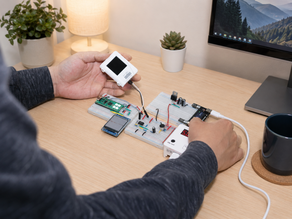
Short answer: A multimeter is enough when you need one steady number: DC voltage, resistance, continuity, or steady current. You need an oscilloscope when a signal changes over time, such as PWM, switching circuits, changing sensor signals, or brief spikes and noise. Many beginners start with a multimeter, but using both together makes it easier to see whether a circuit is correct and how it behaves.
If you are getting started with electronics, you have probably come across two essential instruments: the digital multimeter (DMM) and the oscilloscope. Both appear frequently in electronics laboratories, engineering classrooms, and DIY workspaces. But if you are building your own electronics setup, do you really need both? Can a multimeter handle most of your measurements, or is an oscilloscope worth adding?
The answer depends less on how advanced your project is and more on what you are trying to understand about a circuit. A multimeter is excellent at telling you how much voltage, current, or resistance you have. An oscilloscope goes further by showing how an electrical signal changes over time. These capabilities overlap in some situations, but they answer fundamentally different questions.
1. What Can a Multimeter Measure, and When Is It Enough?
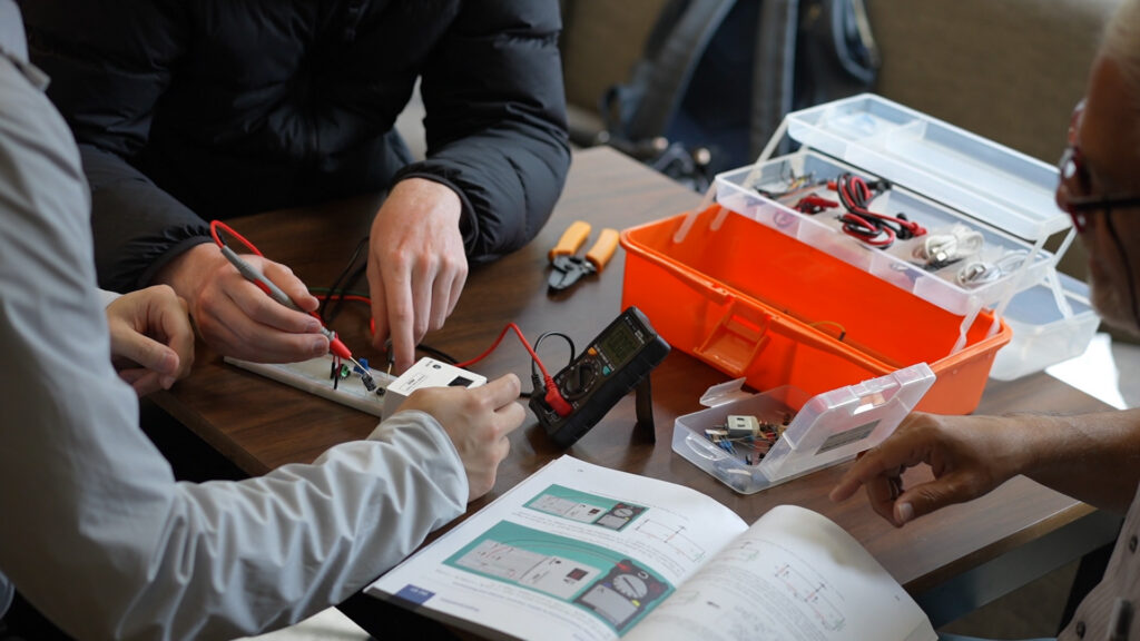
A digital multimeter is often the first measuring instrument students encounter in electronics. It typically measures voltage, current, and resistance, while many models also support continuity testing, diode testing, capacitance, and frequency measurement. Its greatest advantage is that it provides a numerical reading quickly, without requiring you to interpret a waveform.
Suppose you are building a circuit powered by a 5 V supply. You want to check whether the supply is working correctly, whether a voltage divider produces the expected output, or whether a resistor has the correct resistance. A multimeter is usually all you need. For accurate DC voltage measurements, a good DMM can even be more suitable than a general-purpose oscilloscope. Many 3½-digit or 4½-digit multimeters provide useful millivolt-level resolution; higher-resolution models may display smaller changes. But resolution is not accuracy: actual uncertainty depends on the meter, range, and specifications.
This is useful when working with reference voltages, sensor outputs, or circuits where small differences in DC levels matter. An oscilloscope can also measure DC voltage, but its vertical resolution, noise floor, probe configuration, and calibration may limit how precisely it can resolve small differences. If your question is whether a stable reference reads 2.500 V or 2.510 V, a suitable multimeter may be the clearer choice.
A multimeter is also convenient for resistance and continuity testing. You can quickly identify an open connection, check a resistor, or verify that two points are connected. The limitation appears when a signal changes rapidly. A meter typically updates its display only a few times per second. A changing voltage may therefore appear as an average, RMS, or unstable reading, depending on the measurement mode. That number may be valid, but it does not show the complete behavior of the signal.
2. When Do You Actually Need an Oscilloscope?
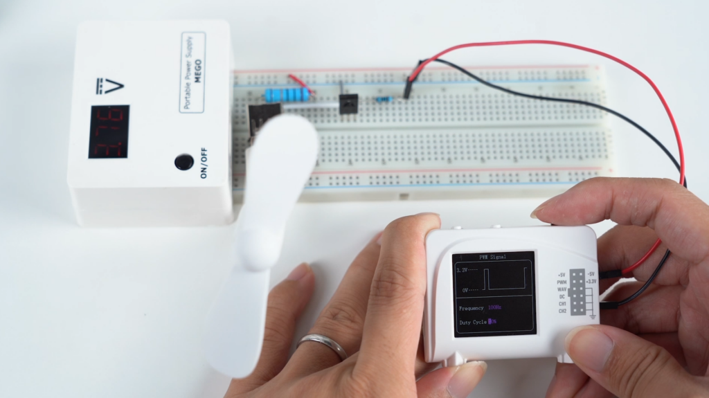
Imagine measuring the output of a microcontroller. A multimeter might show approximately 1.65 V on a 3.3 V PWM signal with a 50% duty cycle. Does that mean the microcontroller is generating a steady 1.65 V output? Not at all. The signal may be switching rapidly between 0 V and 3.3 V, spending half its time at each level. The multimeter reports the average DC component, while the oscilloscope reveals the switching waveform.
This is where an oscilloscope becomes indispensable. Instead of giving you one number, it displays voltage against time. You can observe waveform shape, frequency, amplitude, duty cycle, and timing. You can also identify short spikes, distortion, overshoot, ringing, or brief interruptions that an ordinary multimeter would miss.
| Measurement task | Better starting choice |
|---|---|
| Checking a stable DC supply | Multimeter |
| Measuring resistance or continuity | Multimeter |
| Checking a precise DC reference | Suitable precision DMM |
| Observing PWM or switching signals | Oscilloscope |
| Measuring rise time or transients | Oscilloscope |
| Comparing timing between two signals | Multi-channel oscilloscope |
| Examining frequency components | Oscilloscope with FFT |
An oscilloscope becomes especially valuable when you move from measuring a circuit to understanding its behavior. When testing a filter, you may want to see how a sine wave changes with frequency. When studying an amplifier, you may want to observe clipping. When investigating a digital circuit, you may need to compare two signals and check their timing.
Many digital oscilloscopes also offer mathematical functions and FFT (Fast Fourier Transform) analysis, helping you examine frequency components, harmonics, and unwanted oscillations. FFT does not replace every capability of a dedicated spectrum analyzer, but it provides an excellent introduction to frequency-domain analysis. For students, this is an important transition: instead of asking only “What voltage is present?”, you begin asking “Why does the signal behave this way?”
If you are choosing a first oscilloscope, the EIM guide to the best oscilloscope for beginners explains which specifications matter.
Fundamental EE Starter, FE11
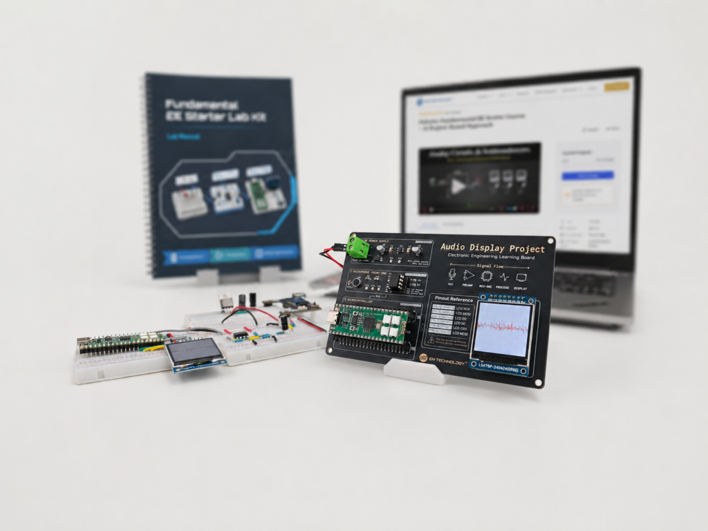
For learners who want a structured way to build that habit, the Fundamental EE Starter kit (FE11) follows one connected path through circuits, analog design, microcontrollers, PCBs, and guided projects, with an online learning platform alongside the hardware. AI can explain each concept along the way, while the kit keeps the learning grounded in real circuits.
3. Current Measurement and Grounding: Two Differences Beginners Overlook
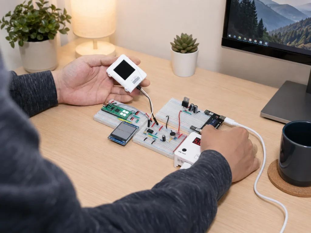
One common misconception is that multimeters measure current while oscilloscopes do not. Both can measure current, but often in different ways. Most multimeters measure current through an internal shunt resistor, requiring you to open the circuit and insert the meter in series. This is straightforward and inexpensive for steady currents, although the added resistance and resulting burden voltage can affect sensitive circuits.
An oscilloscope can measure current with an appropriate current probe, or by measuring voltage across a known shunt resistor. Some probes use Hall-effect sensing to measure both DC and AC current without opening the circuit; other technologies are designed mainly for AC. Professional probes can cost hundreds or thousands of dollars, but they can reveal how current changes over time, such as motor inrush, switching-current pulses, or brief spikes. Clamp multimeters can also measure current without opening a circuit, though typical models do not offer the same waveform display and transient capture capabilities.
Grounding is another major distinction. A battery-powered handheld multimeter typically has floating measurement inputs, so it can measure the voltage between two circuit points without either point being connected to earth ground, provided the instrument’s voltage and safety ratings are respected. A conventional bench oscilloscope is different: its probe ground is usually connected to protective earth. Attaching that ground clip to the wrong point can short part of a circuit to earth and create a serious hazard.
Some portable oscilloscopes offer floating or isolated measurement arrangements, depending on their design. Battery power alone does not guarantee isolation. Always check the instrument’s grounding architecture and ratings rather than assuming that a portable device can safely measure any two points.
4. Why Does Having Both Instruments Make Electronics Learning Easier?
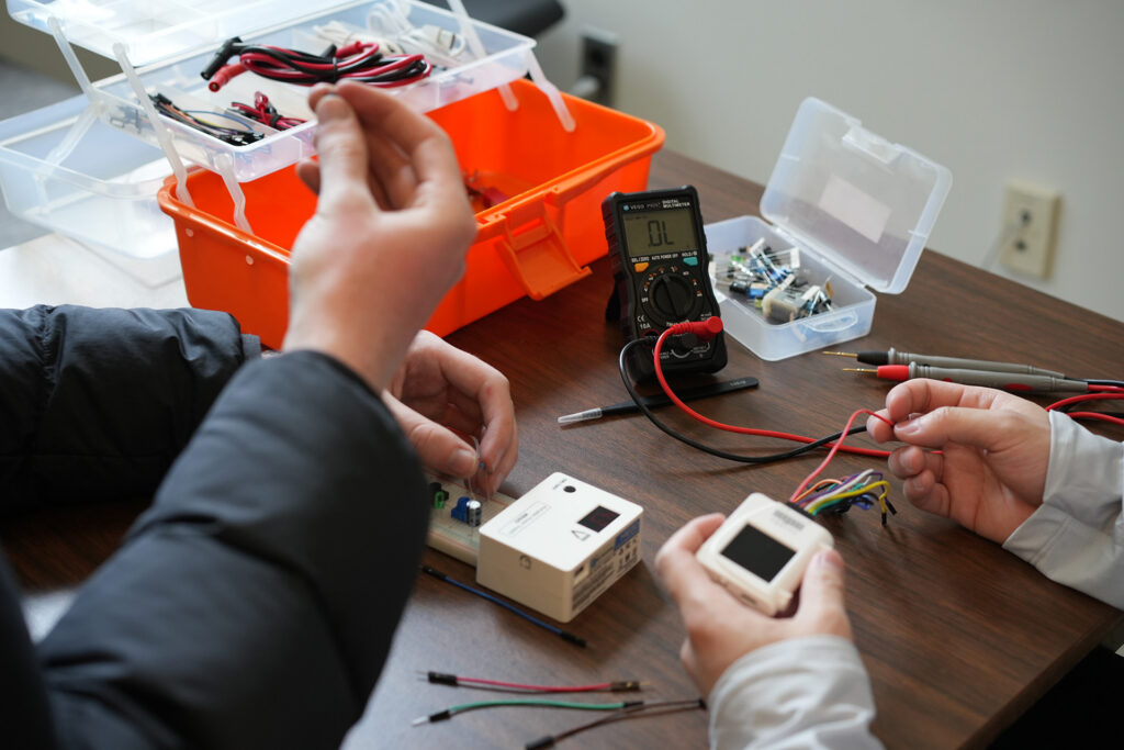
For many projects, the best solution is not to choose between a multimeter and an oscilloscope, but to use them together. Consider a student building a sensor circuit with a microcontroller. First, the student checks the supply with a multimeter, verifies resistor values, and confirms the wiring. Once the circuit is running, an oscilloscope reveals the sensor output, unwanted noise, or how the signal changes when the sensor responds to its environment.
The two instruments serve different stages of the same experiment. The multimeter helps establish whether the circuit is electrically correct; the oscilloscope helps explain how it behaves. This becomes more important as students progress beyond LEDs and switches into sensors, signal processing, embedded systems, and analog electronics. A circuit may have the correct supply voltage and still fail because of signal timing, unexpected oscillation, or a brief transient.
For teachers, the combination opens up meaningful demonstrations: compare steady DC with PWM, watch an RC circuit charge and discharge, or investigate the differences between sine and square waves. Yet a traditional workbench can require several instruments, probes, cables, and accessories. For a student at home, a teacher preparing portable demonstrations, or a hobbyist with limited workspace, cost and setup effort can become barriers. The objective is not necessarily to recreate a professional laboratory; it is to have enough measurement capability to explore the fundamentals without spending most of your time setting up equipment. For a broader look at what a first electronics lab needs, see how to build an electronics lab.
5. A More Practical Starting Point: Lab-on-the-Go
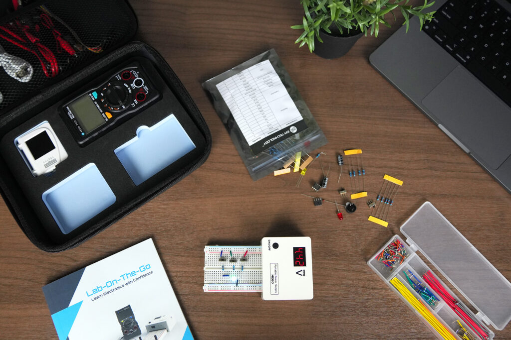
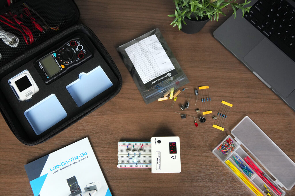
This is the idea behind Lab-on-the-Go from EIM Technology. Rather than requiring beginners to assemble a workbench from separate professional instruments, Lab-on-the-Go brings together three essential tools in a portable system: a digital multimeter, a compact oscilloscope with signal-generation capabilities, and an adjustable, rechargeable power supply.
The multimeter handles everyday electrical measurements, including voltage, current, resistance, and continuity. The oscilloscope allows students to observe waveforms, investigate timing, and explore frequency-domain concepts. The power supply provides a convenient way to power and test circuits. Together, these instruments cover many measurements encountered while learning fundamental electronics and experimenting with microcontrollers, sensors, and simple analog or digital systems.
Lab-on-the-Go is not intended to replace a high-end professional oscilloscope or precision laboratory multimeter. Very high frequencies, extremely small signals, demanding accuracy requirements, or hazardous electrical environments may require specialized equipment. But for introductory electronics education, classroom demonstrations, and many low-voltage DIY projects, a portable integrated setup can be much more convenient than a traditional collection of bench instruments.
For students preparing to study electronics or computer engineering, teachers developing hands-on STEM activities, and hobbyists who want to move beyond assembling circuits into understanding how they work, this combination offers a practical starting point. You do not need a fully equipped professional laboratory to begin exploring electronics seriously. You need the right tools, an understanding of what each instrument can tell you, and opportunities to apply them to real circuits.
Why choose Lab-on-the-Go instead of separate bench instruments?
- Three instruments, four lab capabilities. The VEGO auto-ranging multimeter, the Zoolark two-channel oscilloscope and waveform generator, and the MEGO rechargeable power supply (adjustable 4–24 V DC) cover measurement, signal observation, signal generation, and power.
- Parts included to start building. The kit also includes a 410-hole breadboard, electronic components, cables and test leads, a quick-start guide, and an EVA carrying case.
- One kit price. Lab-on-the-Go is approximately US$229 (CA$309 MSRP, billed in CAD), with free shipping in the United States and Canada.
Lab-on-the-Go is also compatible with the Fundamental EE Starter (FE11).
Frequently Asked Questions
Can I use a multimeter instead of an oscilloscope?
Yes, for stable DC voltages, resistance, continuity, and steady current. For waveforms, switching behavior, or brief changes, an oscilloscope provides information a conventional multimeter cannot.
Do beginners really need an oscilloscope?
Not necessarily on day one. Simple DC circuits may need only a multimeter. Once you work with PWM, sensors, microcontrollers, filters, or changing analog signals, an oscilloscope becomes much more useful.
Can an oscilloscope measure DC voltage and current?
Yes. It measures DC voltage within its input limits and can measure current with a suitable probe or shunt resistor. For accurate steady DC readings, a good multimeter is often more convenient.
Is a portable oscilloscope good enough for electronics learning?
Often, for low-voltage projects. Check bandwidth, sampling capability, input range, accuracy, and grounding design against the signals you intend to study.

EIM TECHNOLOGY
Founder & Engineering Education Innovator
Daniel Cao is the Founder of EIM Technology and holds a Master of Applied Science in Engineering. With experience in engineering research, product development, PCB design, and technical education, he is the author of several books on electronics engineering. His work focuses on developing practical learning systems that integrate engineering hardware, lab instruments, curriculum, and project-based learning. Through EIM Technology, Daniel aims to make electronics and computer engineering more accessible and engaging, helping students build real experience in designing, measuring, testing, and troubleshooting electronic systems.