Why So Many types of resistor Resistors?
Building on our previous discussion, let's delve deeper into the materials and processes behind each type of resistor.
Discovering each types of resistors:
Wire wound resistors
Wire wound resistors are made by winding high resistivity wire such as constantan, manganese-copper, or nickel-chromium alloy wire around a ceramic core. Some of these resistors are coated with a layer of glass enamel, commonly known as vitreous enamel wire wound resistors. Some are coated with a layer of protective organic or clear varnish, known as painted wire wound resistors. Others are made with unprotected bare wire winding, known as bare wire wound resistors. The surface covering the cap not only provides protection for the resistor but also helps maintain its resistance stability when the conditions of the resistor wire change in the working environment. The outer appearance and internal structure of wire wound resistors are shown in Figure 1.

Figure 1. The External Appearance and Internal Structure of Wire Wound Resistors
Wire wound resistors have low noise, even no current noise; low temperature coefficient, good thermal stability, high temperature resistance, and can operate at temperatures up to 315°C; they have high power handling capability and can withstand high power loads; resistance ranges from 0.01Ω to 100kΩ; rated power ranges from 1/8 to 500W. Their disadvantage is poor high-frequency performance.
Organic Solid Resistors
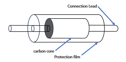
Organic Solid Resistors are made by mixing conductive materials such as carbon black, graphite, etc., with fillers and organic binders to form a powder mixture. After being hot-pressed by specialized equipment, they are enclosed in plastic shells. The leads of the solid resistor are molded into the resistor body. There are two types: one is a resistor without end caps, and the other is a resistor with end caps used as electrodes. The external appearance and internal structure of organic solid resistors are as shown in the figure. Organic solid resistors have high mechanical strength, good reliability, strong overload capacity, small size, and low price. However, they have high noise, large distributed parameters, and poor voltage and temperature stability. The resistance range is from 4.7Ω to 22MΩ, the operating voltage is from 250 to 500V, and the rated power is from 1/4 to 2W. This type of resistor is not suitable for use in circuits that require high precision. Common organic solid resistors include RS11 and RS types, with RS type commonly used in automotive instruments (such as oil pressure gauges).

Figure 2. The External Appearance and Internal Structure of Organic Solid Resistors
The structure of Inorganic Solid Resistors is basically the same as that of organic solid resistors, except for the material. Organic solid resistors are made by mixing materials such as granular conductors (such as carbon black, graphite), fillers (such as mica powder, quartz powder, glass powder, titanium dioxide (TiO2), etc.), and organic adhesives (such as phenolic resin, etc.), and then hot-pressing them into shape. They have strong overload resistance. Inorganic solid resistors are made by mixing conductive materials (such as carbon black, graphite), fillers, and inorganic adhesives (such as glass enamel, etc.), pressing them into shape, and then sintering them at high temperatures. They have a larger temperature coefficient but a smaller resistance range.
Carbon film Resistors
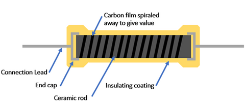
Carbon Film Resistors are made by depositing crystalline carbon, obtained through vacuum high-temperature decomposition, onto cylindrical or tubular ceramic cores. The resistance is controlled by adjusting the thickness of the film and the grooves. The external appearance and internal structure of carbon film resistors are shown in the figure3. These resistors mainly consist of a layer of carbon mixture film formed on a ceramic rod. The thickness and carbon concentration of the carbon film can control the resistance. Spiral grooves can be processed on the carbon film, where more spirals lead to higher resistance. Finally, metal leads are added to the alumina ceramic rod, and the whole structure is encapsulated in resin. Carbon film resistors exhibit good stability, low negative temperature coefficient, excellent high-frequency characteristics, minimal susceptibility to voltage and frequency variations, low noise electromotive force, stable performance under pulse loads, a wide range of resistance values, simple manufacturing processes, and low production costs. Consequently, they find extensive applications across various electronic products.

Figure 3. The External Appearance and Internal Structure of Carbon Film Resistors
Metal film resistor
Metal Film Resistors are made by depositing a layer of metal or alloy material onto a ceramic substrate through processes like vacuum heating evaporation, high-temperature decomposition, chemical deposition, or sintering. Metal film resistors exhibit good stability and heat resistance, low temperature coefficient, wide operating frequency range, and minimal noise electromotive force. They are commonly used in high-frequency circuits.
Metal oxide film resistor
The manufacturing process of Metal Oxide Film Resistors is as follows: metal or alloy is used as the resistor material, and vacuum evaporation or sputtering methods are employed to form an oxide resistor film layer on a ceramic or glass substrate. The conductive film layer of metal oxide film resistors is uniform, and it firmly bonds with the substrate. Some properties of metal oxide film resistors are superior to those of metal film resistors. The external appearance and internal structure of typical metal oxide film resistors are similar to those of metal film resistors, often cylindrical with axial lead-out wires. Metal oxide film resistors have stronger oxidation resistance and better resistance to acid and salt, as well as good heat resistance compared to metal film resistors. However, their drawback lies in the limited resistance range due to material characteristics and film thickness, resulting in a resistance range of 1Ω to 200kΩ.
Glass glaze resistor
Glass Glaze Resistors are made by mixing metal oxides of metals like silver, rhodium, and ruthenium with glass enamel binders to form a paste. This paste is then coated onto ceramic substrates and fired at high temperatures to create the resistor. Currently, glass glaze resistors are mostly produced using oxides and glass enamel binders. There are two main types of glass glaze resistors: standard and precision types. Their external appearance and internal structure are depicted in the figure. Glass glaze resistors have poor heat resistance but good moisture resistance, excellent stability, low noise, small temperature coefficients, and a wide resistance range from 4.7Ω to 200MΩ. They are available in various power ratings including 1/8W, 1/4W, 1/2W, 1W, 2W, and high-power versions up to 500W, with a maximum voltage of 15kV.


