Let us understand what is a half wave rectifier. To start with let us look at what is a simple rectifier and what does it do.
What is a Rectifier?
Rectification refers to converting AC to DC, and the electrical device that fulfills this task is called a rectifier. As expected, rectifiers are used in various electronic devices and systems to provide the DC power necessary for electronic components and circuits.
Definition of a Rectifier:
A rectifier is an electronic device that converts an alternating current into a direct current using one or more P-N junction diodes.
How does a half-wave rectifier work?
Let us look at the half wave rectifier without a capacitor and see what’s the output across the load RL via scope:

An ac input that a sine wave is fed to the circuit.
- During the positive half cycle: Cathode is forward biased – the current flows across the diode in the positive half cycle. The diode conducts in forward bias and there is current in the RL.
- During the negative half-cycle (when no current is flowing through the diode), the rectifier’s output would normally drop to zero. The diode is revered biased and no current flows through the resistor.
In the negative half cycle of the supply, no current flows in the load resistor as no voltage appears across it so therefore, Vout = 0.
Why a capacitor is used in a rectifier circuit? How a capacitor smoothens the ripple in a rectifier out?
A capacitor is used in a rectifier circuit to smooth the output and reduce the ripple in the DC voltage. As seen in this circuit, the output is not a steady DC voltage but rather a pulsating DC with significant fluctuations (ripple). To make the DC output more constant and stable, a capacitor is used as a filter.

The image shows a half-wave rectifier using a standard signal diode (1N4148) to observe the rectified output. In one image there is simple rectification with no capacitor and the other is a rectifier with a capacitor giving continuous DC instead of pulsating DC output.
Specially, in this case, the output of a half-wave rectifier is 𝗽𝘂𝗹𝘀𝗮𝘁𝗶𝗻𝗴 𝗗𝗖, which means the output voltage rises and falls with the input AC waveform. This makes it unsuitable for many applications that require a more steady DC voltage.
Let us see what happens with addition of filter capacitor:
- Charging during the Positive Half-Cycle:
Cathode is forward biased – the current flows across the diode in the positive half cycle. When the rectifier produces a positive half-cycle, the capacitor charges up to the peak voltage of the rectified signal. Once the voltage across the capacitor reaches the peak value of the rectified waveform, the capacitor starts to store that energy.
Since the DC load is resistive (resistor, R), the current flowing in the load resistor is therefore proportional to the voltage (Ohm´s Law), and the voltage across the load resistor will therefore be the same as the supply voltage, Vs (minus Vƒ), that is the “DC” voltage across the load is sinusoidal for the first half cycle only so Vout = Vs.
- Discharging during the Negative Half-Cycle:
During the negative half-cycle (when no current is flowing through the diode), the rectifier’s output would normally drop to zero. However, the capacitor begins to discharge slowly through the load (resistor or circuit), supplying voltage during the periods when the input is zero or low. This discharging action fills the gap between the positive pulses, smoothing the output waveform.
In the negative half cycle of the supply, no current flows in the load resistor as no voltage appears across it so therefore, Vout = 0.
𝗜𝗺𝗽𝗮𝗰𝘁 𝗼𝗻 𝘁𝗵𝗲 𝗢𝘂𝘁𝗽𝘂𝘁:

- 𝗪𝗶𝘁𝗵𝗼𝘂𝘁 𝗮 𝗖𝗮𝗽𝗮𝗰𝗶𝘁𝗼𝗿: The output of a half-wave rectifier is pulsating DC, which means the output voltage rises and falls with the input AC waveform. This makes it unsuitable for many applications that require a more steady DC voltage.
- 𝗪𝗶𝘁𝗵 𝗮 𝗖𝗮𝗽𝗮𝗰𝗶𝘁𝗼𝗿: The capacitor helps to maintain a higher voltage level across the load by storing energy during the peaks of the rectified output and discharging during the valleys (where the input signal would normally fall to zero). The output waveform becomes much smoother with less ripple, making it more like a constant DC voltage.
software simulation tool used https://www.falstad.com/circuit/
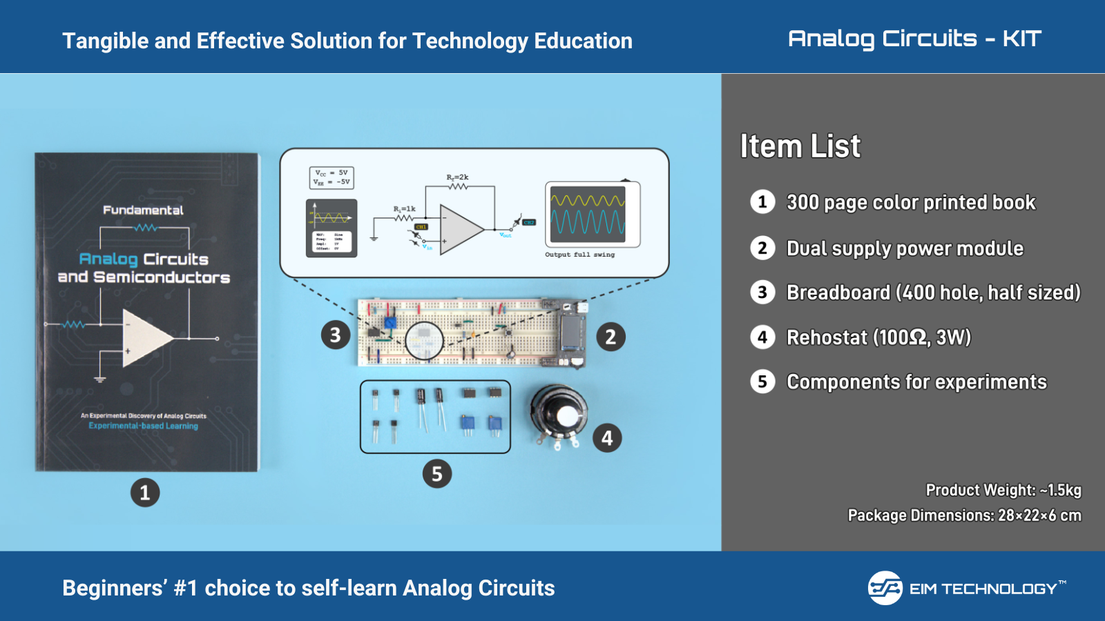
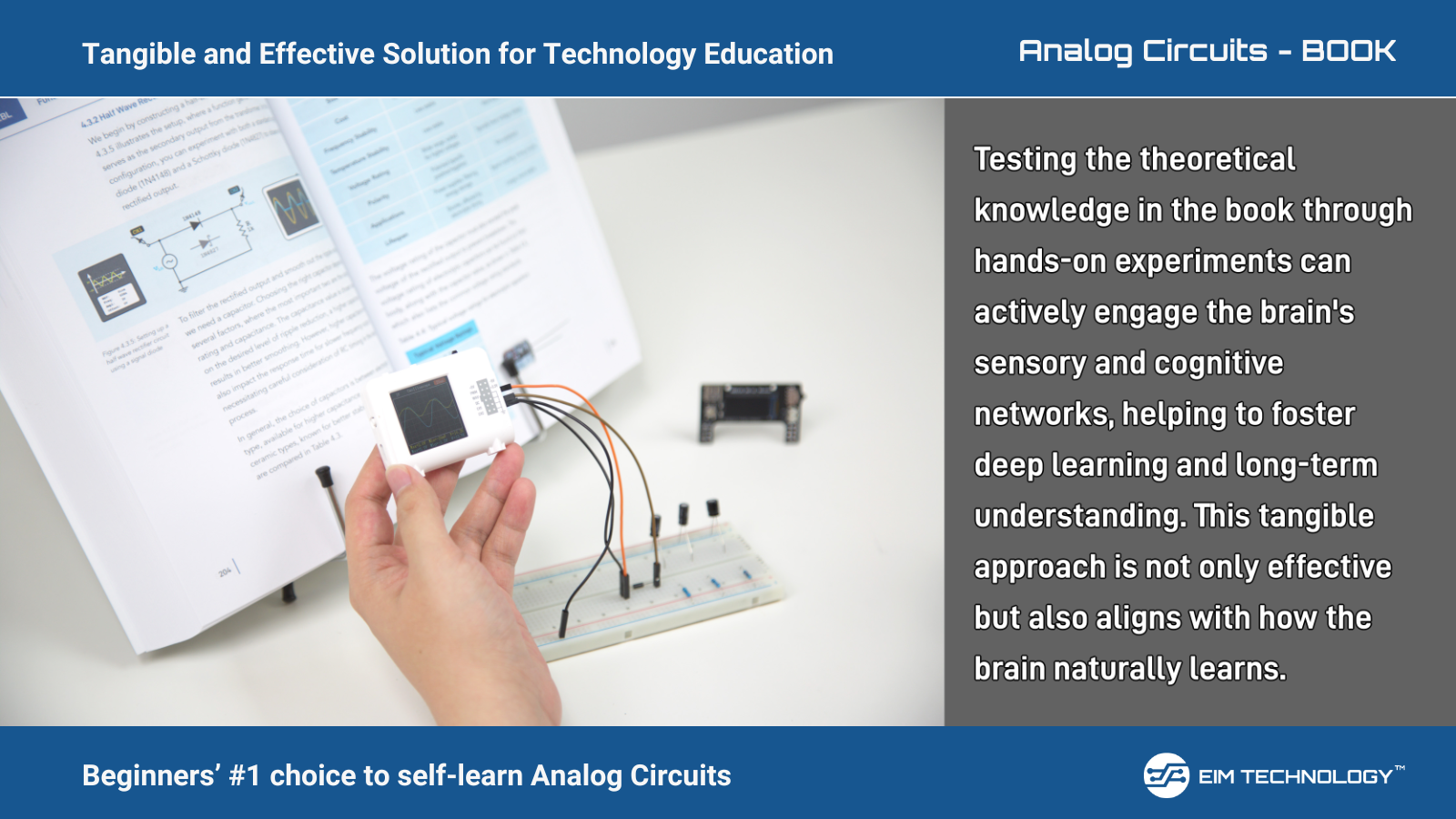
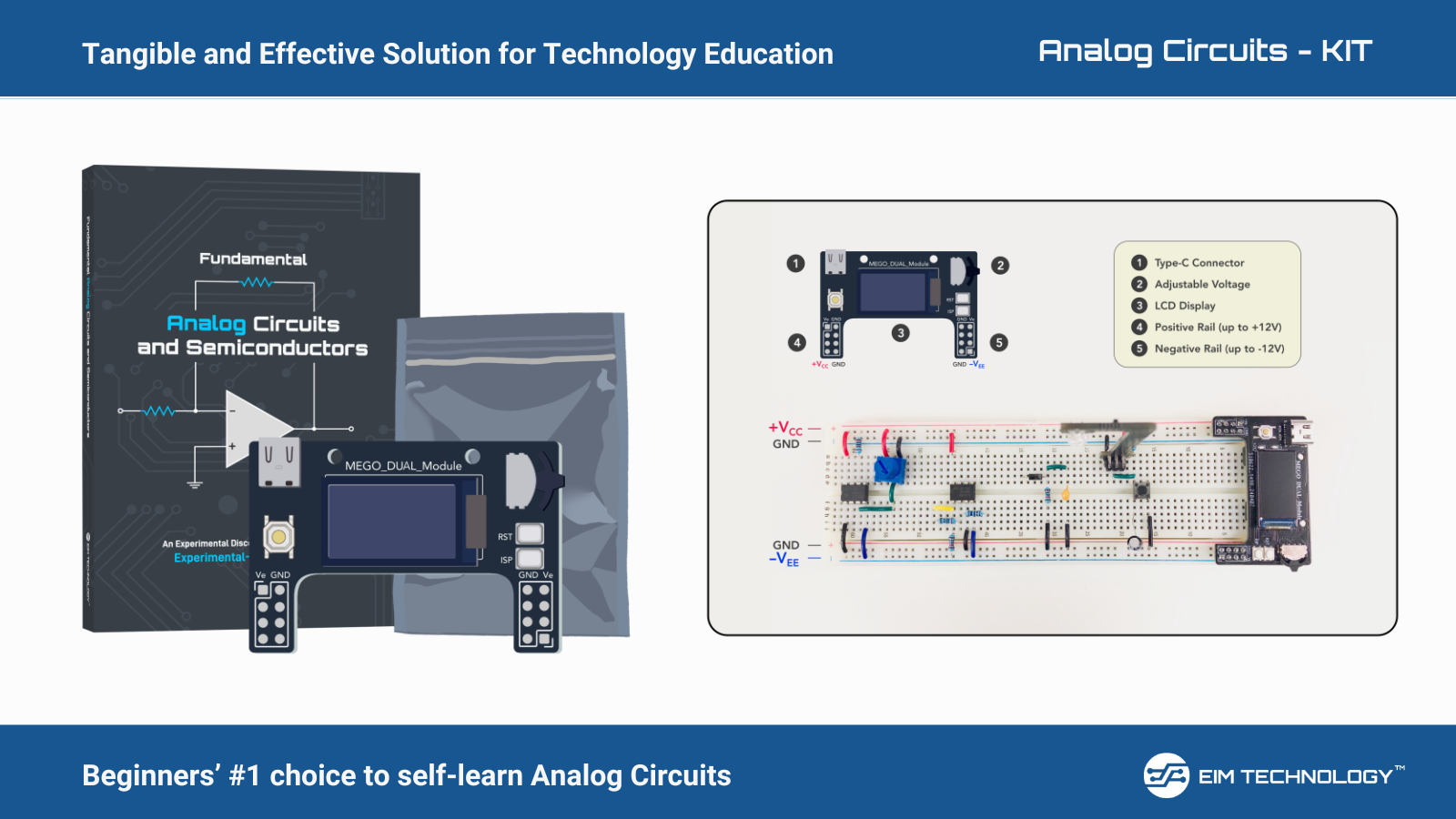
Similar circuits are explained in our tutorial book which comes along with our Learning Kit, where you can get the opportunity to implement this circuit practically. Check Analog Circuit kit: https://www.eimtechnology.com/collections/all-products/products/fundamental-analog-circuits-semiconductors?variant=48782064877887
Half Wave Rectifier Formulae:
✦ Average output voltage of a half wave rectifier

✦ RMS value of the output voltage of a half wave rectifier

✦ Ripple Factor of Half Wave Rectifier
Ripple factor determines how well a halfwave rectifier can convert AC voltage to DC voltage. Ripple factor can be quantified using the following formula:

The ripple factor of a halfwave rectifier is 1.21, indicating a considerable amount of ripple in the output. compared to the DC component.
The ripple factor is important because it indicates the level of AC ripple in the DC output of a rectifier. A high ripple factor means more ripple is present, which can lead to:
- Poor Performance: Inconsistent DC voltage can affect the performance of electronic devices and circuits.
- Component Stress: Excessive ripple can stress and potentially damage sensitive components.
- Noise: Ripple can introduce unwanted noise into audio and signal processing circuits.
- Power Quality: For power supplies, minimizing ripple is crucial for stable and reliable operation.
✦ Efficiency of Halfwave Rectifier
The efficiency of a halfwave rectifier is the ratio of output DC power to the input AC power.
The efficiency formula for halfwave rectifier is given as follows;

The efficiency will be maximum if rf is negligible as compared to RL. Max. rectifier efficiency = 40.6 %. This shows that in half-wave rectification, a maximum of 40.6 % of a.c. power is converted into d.c. power. This is because the half-wave rectifier only utilizes half of the AC waveform and produces a significant amount of ripple, leading to lower overall power conversion efficiency.
Why is Efficiency of a rectifier important?
Efficiency is important because it indicates how well a rectifier converts AC power into usable DC power. A higher efficiency means more of the input power is effectively used for the load, while less is wasted as heat. This is crucial for:
- Energy Conservation: Higher efficiency reduces energy loss, which is especially important in power-sensitive applications and for minimizing operating costs.
- Heat Management: Lower efficiency leads to more heat generation, which can require additional cooling and impact the longevity of components.
- Power Supply Design: In designing power supplies, higher efficiency means a more compact and cost-effective design with better overall performance.
✦ RMS value of load current of Half Wave Rectifier
The RMS value of the load current for a half-wave rectifier is given by the formula:

✦ Form factor of a Halfwave Rectifier
The form factor is the ratio between RMS value and average value and is given by the formula:

✦ Peak Inverse Voltage (PIV) of half wave rectifier
Peak Inverse Voltage (PIV) is the maximum voltage a diode can handle when it is reverse-biased without being damaged. In a half-wave rectifier, during the negative half of the AC cycle, the diode is reverse-biased and blocks current flow. At this time, the entire input voltage appears across the diode. Therefore, the maximum voltage the diode must withstand in this condition is equal to the peak value of the input AC voltage (Vm). Thus, for a half-wave rectifier, the PIV rating must be at least equal to Vm to ensure the diode’s safety and proper function. Thus the maximum voltage, that appears across the diode, is equal to the peak value of the secondary voltage i.e. Vm. For a half-wave rectifier;
Peak Inverse Voltage (PIV) = Vm
Applications of Half Wave Rectifier
Most common use that we see is Halfwave rectifiers are used along with step-up and step-down transformers to achieve the desired voltage. It is also used in low-power devices, signal demodulation, and circuits requiring simple AC to DC conversion.
- Power Supplies: For small electronic devices and gadgets.
- Signal Demodulation: In AM radio receivers for extracting audio signals.
- Battery Chargers: For low-current charging applications.
- Voltage Doublers: In circuits where basic rectification is needed.
- Measurement Instruments: As part of simple AC voltmeters or watt meters.
- Signal peak applications
Disadvantages of Half Wave Rectifier
- Power loss
- Low output voltage
- The output contains a lot of ripples
✦ Frequently Asked Questions
- What is rectification in electronics?
Rectification in electronics is the process of converting alternating current (AC) into direct current (DC). This is typically done using diodes, which allow current to flow in only one direction, turning the AC's bidirectional flow into a unidirectional flow suitable for DC-powered devices.
- What is a rectifier?
A rectifier is an electronic device that converts an alternating current into a direct current using one or more P-N junction diodes.
- What is the difference between a half wave rectifier and a full wave rectifier?
The main differences between a half-wave rectifier and a full-wave rectifier are:
- Half-Wave Rectifier: Only allows one half of the AC waveform (either positive or negative) to pass through, resulting in a pulsating DC with more ripple. It's less efficient and provides lower output voltage.
- Full-Wave Rectifier: Allows both halves of the AC waveform to be used by inverting the negative half, producing smoother DC output with less ripple. It's more efficient and provides higher output voltage.
- What is Peak Inverse Voltage (PIV)?
Peak Inverse Voltage (PIV) is the maximum voltage a diode can withstand in the reverse-biased direction without breaking down. In rectifier circuits, PIV is important because it determines the maximum voltage the diode can block when it's not conducting.
- What is the ripple factor?
The ripple factor measures the fluctuations in the rectified DC output, indicating the level of pulsation and quality of rectification. The ripple factor is a measure of the residual AC component (ripple) in the output of a rectifier. It indicates how smooth the rectified DC output is. Mathematically, it is the ratio of the RMS value of the AC component to the DC component in the rectified output. A lower ripple factor means a smoother DC signal.
- What are some common issues in rectifier circuits and how can they be troubleshooted?
Common issues in rectifier circuits and their troubleshooting methods include:
- Excessive Ripple: Caused by insufficient filtering. Troubleshoot by adding or improving filter capacitors to smooth the output. An oscilloscope to measure the ripple frequency at the rectifier output.
- Overheating Diodes: May occur due to exceeding current ratings. Check for proper diode ratings and ensure good heat dissipation or cooling mechanisms. .You can use a multimeter to check diode.
- Low Output Voltage: Could be due to a faulty diode or poor transformer. Test diodes for correct operation and ensure the transformer provides the correct input voltage.
- Reverse Breakdown of Diodes: Caused by exceeding Peak Inverse Voltage (PIV). Use diodes with a higher PIV rating to prevent failure.
- No Output: Could result from open circuits or a faulty diode. Test all components in the rectifier and replace any malfunctioning ones.
- What is a half wave rectifier?
A half-wave rectifier is a simple circuit used to transform AC (alternating current) into DC (direct current). It permits only one half of the input sine wave (either the positive or negative portion) to pass through, while blocking the other half. This produces a pulsating DC output, meaning the current isn’t completely smooth but varies with the shape of the input waveform.
- Where is a halfwave rectifier used?
Most common use that we see is Halfwave rectifiers are used along with step-up and step-down transformers to achieve the desired voltage. It is also used in low-power devices, signal demodulation, and circuits requiring simple AC to DC conversion.
Some common applications of a half-wave rectifier:
- Power Supplies: For small electronic devices and gadgets.
- Signal Demodulation: In AM radio receivers for extracting audio signals.
- Battery Chargers: For low-current charging applications.
- Voltage Doublers: In circuits where basic rectification is needed.
- Measurement Instruments: As part of simple AC voltmeters or watt meters.
- How does a half-wave rectifier work?
A half-wave rectifier works by allowing only one half of the AC waveform (either positive or negative) to pass through while blocking the other half. It uses a diode to conduct during one half-cycle and block during the other, converting AC to pulsating DC.
- Is the half-wave rectifier better or the full-wave rectifier?
A full-wave rectifier is generally better than a half-wave rectifier. It provides a smoother DC output with less ripple and higher efficiency, as it utilizes both halves of the AC waveform, while a half-wave rectifier only uses one half.
- What is the use of a filter in a half-wave rectifier?
A filter in a half-wave rectifier smooths out the pulsating DC output, reducing ripple and providing a more stable DC voltage. In short, the filter circuit (capacitor) in a half-wave rectifier smoothens the pulsating fluctuating DC component.