Today we are going to discuss the simple Adjustable Switching Voltage Regulators circuit which is put together by V. R. Krause in the Wireless World Magazine in May 1976.
What are Simple Switching Voltage Regulators?
Switching voltage regulators are an essential circuit for efficiently generating stable supply voltages and for translating voltages up or down.
Simple LM 7805 Voltage Regulator - Adjustable Switching Voltage Regulators back in 1970s:
Adjustable switching voltage regulators are a type of voltage regulator used in electronics to convert an input voltage to a desired output voltage. Unlike fixed voltage regulators, adjustable regulators allow the output voltage to be set to a specific value using external components, typically resistors or a potentiometer.

--V. R. Krause, "Adjustable Voltage Switching Regulator," Wireless World, May 1976, p. 80.
Let's go through the above schematic in detail, focusing on each section of the circuit and how they work together to achieve a stable, adjustable output voltage.
- AC to DC Conversion
- Transformer: Steps down the mains voltage to 20V AC.
- Bridge Rectifier: Comprising four diodes, it converts the AC voltage to pulsating DC.
- Filtering Capacitor (4400 µF): Smooths the pulsating DC to a more stable DC voltage. This capacitor has a large value to reduce the ripple voltage significantly.
- Voltage Regulation and Switching
- Transistor (TIP5530): Acts as a switch in the switching regulator. It rapidly turns on and off to control the energy transferred to the load.
- Inductor (1 mH): Works with the transistor and capacitors to filter and smooth the output voltage. The inductor stores energy when the transistor is on and releases it when the transistor is off.
- Voltage Regulator (LM109 or 7805): Provides a stable reference voltage. It is a crucial part of the circuit to ensure the output voltage remains stable despite variations in input voltage or load current.
- Feedback and Adjustment Circuit
- Capacitor (30 nF): Works with the feedback loop to stabilize the voltage regulation.
- Resistor Network:
- R1 (470 Ω) and R2 (560 Ω): Form a voltage divider that feeds back a portion of the output voltage to the regulator. This feedback is essential for maintaining regulation and stability.
- R3 (7 Ω): Sets a baseline for the feedback network.
- R4 (680 Ω, adjustable): Allows fine-tuning of the output voltage. By adjusting R4, you change the feedback ratio, which in turn adjusts the output voltage.
- Zener Diode D1: Provides a stable reference voltage to the feedback network, ensuring that the feedback remains accurate and consistent.
- Output Filtering and Load
- Output Capacitor (2200 µF): Ensures that the output voltage is smooth and free of high-frequency noise. This capacitor works in conjunction with the inductor to filter the switching noise.
- Load Resistor (150 Ω): Represents the load connected to the power supply. It ensures there is always a minimum load on the regulator, which helps maintain stability.
Adjustable Switching Voltage Regulators i.e. 7805 Voltage Regulator Detailed Working Process
- Rectification and Filtering:
- The AC voltage is converted to DC by the bridge rectifier and then smoothed by the large 4400 µF capacitor.
- Regulation and Switching:
- The regulated DC voltage is fed into the switching transistor (TIP5530). The switching action of the transistor, controlled by the voltage regulator and the feedback network, rapidly switches the inductor on and off.
- When the transistor is on, current flows through the inductor, storing energy in its magnetic field.
- When the transistor switches off, the inductor releases the stored energy, smoothing the output voltage.
- Feedback and Adjustment:
- The feedback network (R1, R2, and the Zener diode) monitors the output voltage and adjusts the switching transistor's operation to maintain a stable output.
- By adjusting R4, you change the voltage at which the regulator adjusts the switching transistor, thus changing the output voltage.
- Final Filtering:
- The final output passes through the 2200 µF capacitor, which smooths any remaining ripple and noise, providing a clean DC output for the load.
This circuit effectively combines linear and switching regulation techniques. The linear regulator ensures a stable reference voltage, while the switching regulator efficiently steps up or down the voltage to the desired level. The feedback mechanism ensures that the output voltage remains stable under varying load conditions, and the adjustable resistor allows fine-tuning of the output voltage. This design is efficient and versatile, making it suitable for a wide range of applications requiring stable, adjustable DC power.
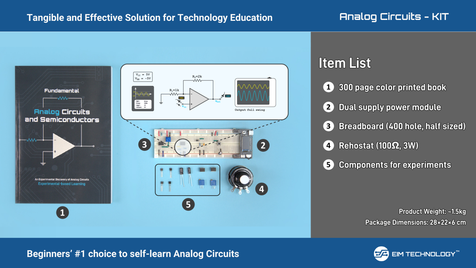
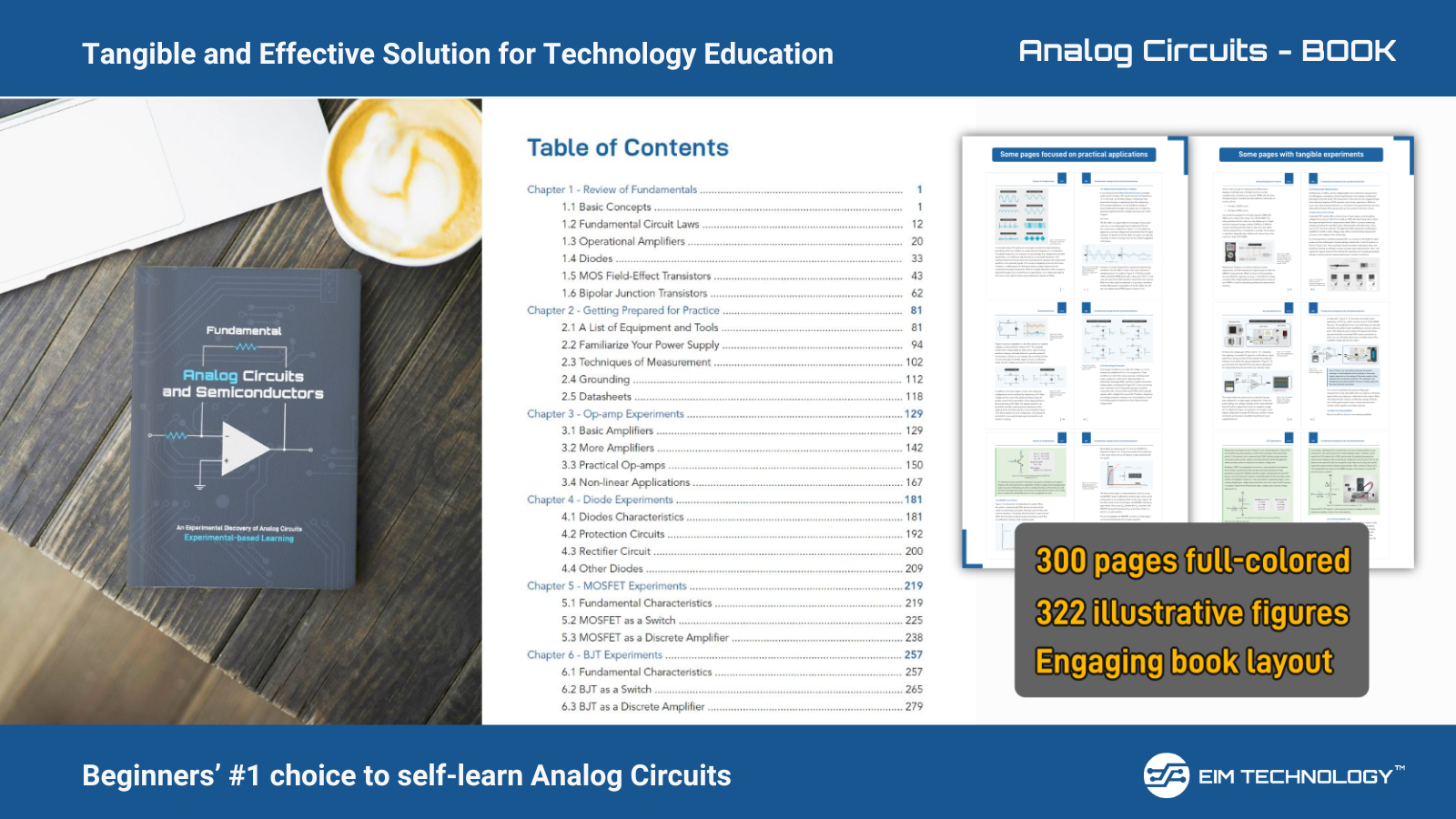
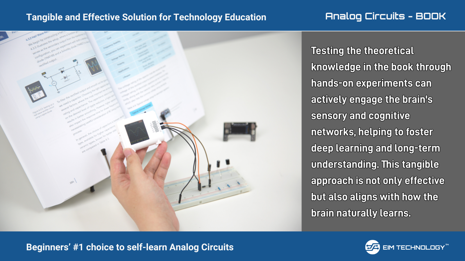
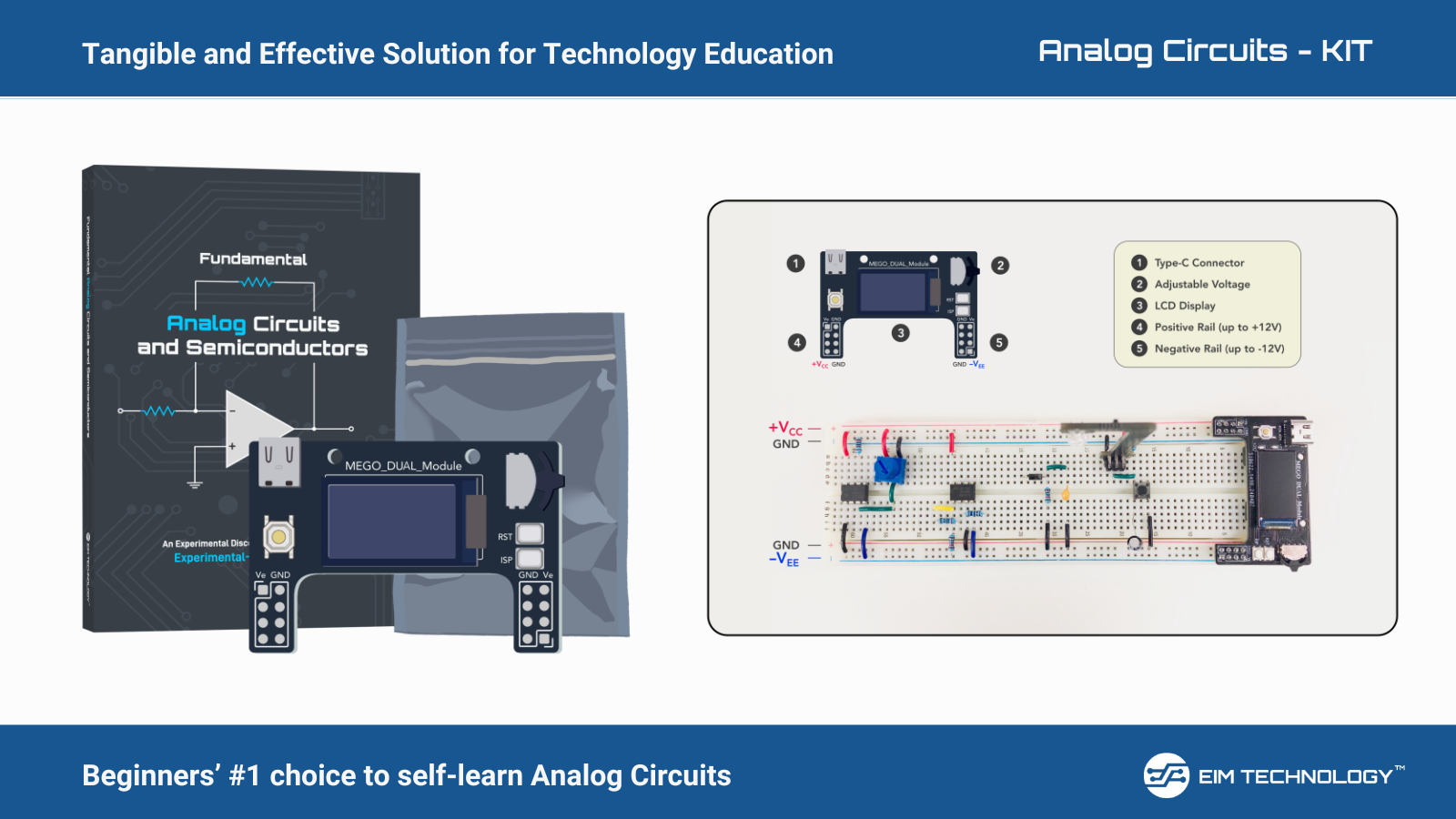
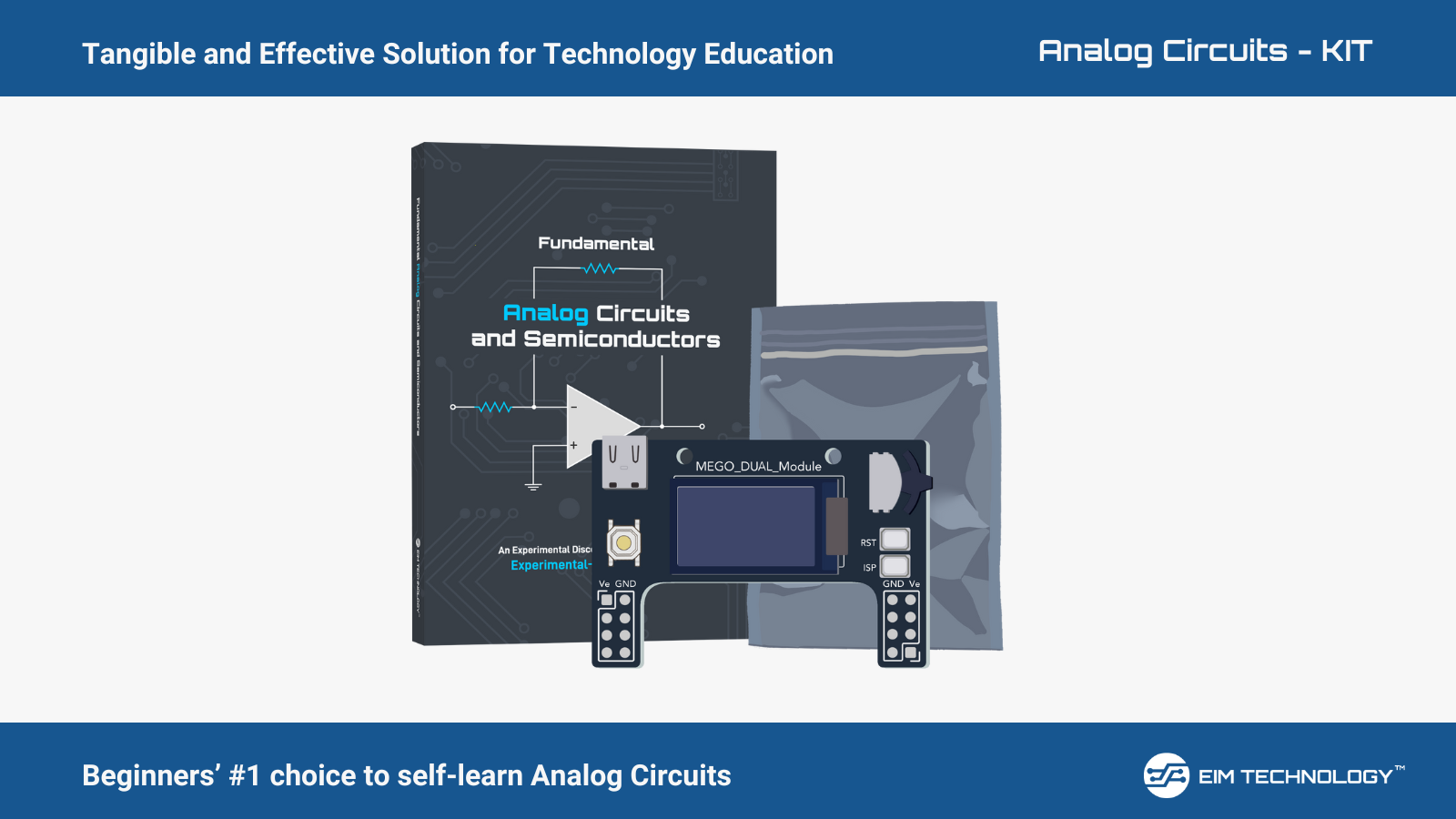
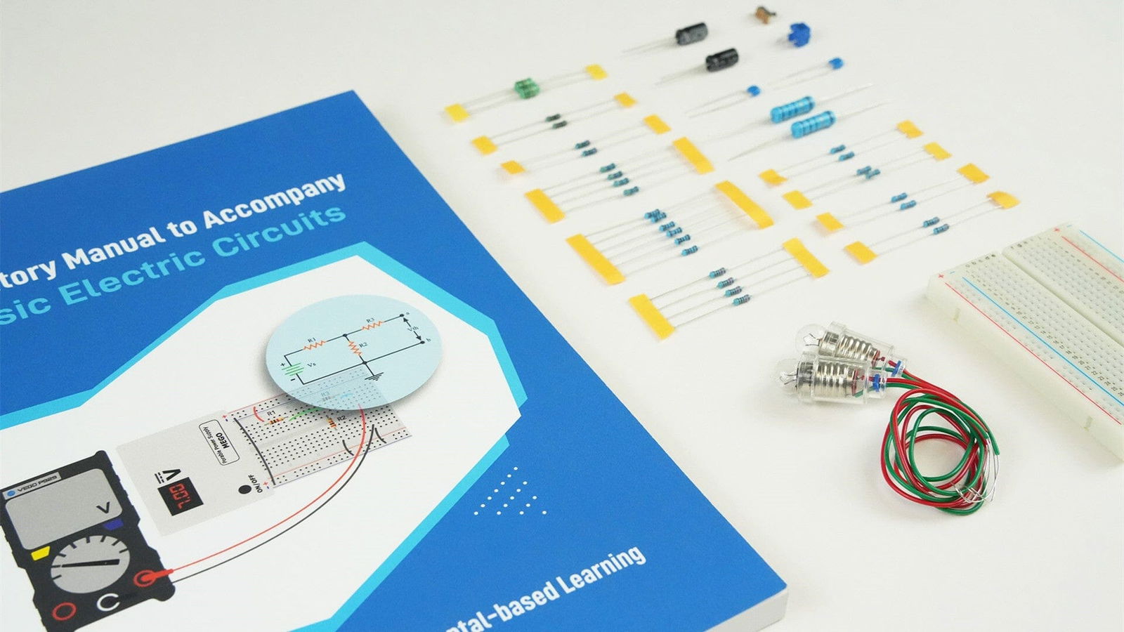
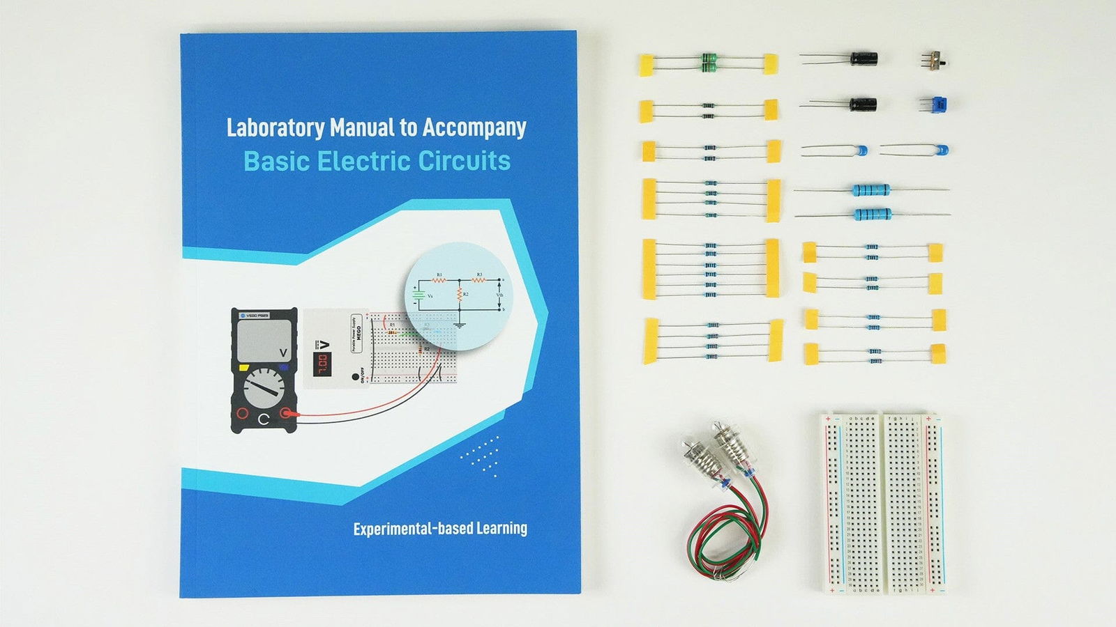
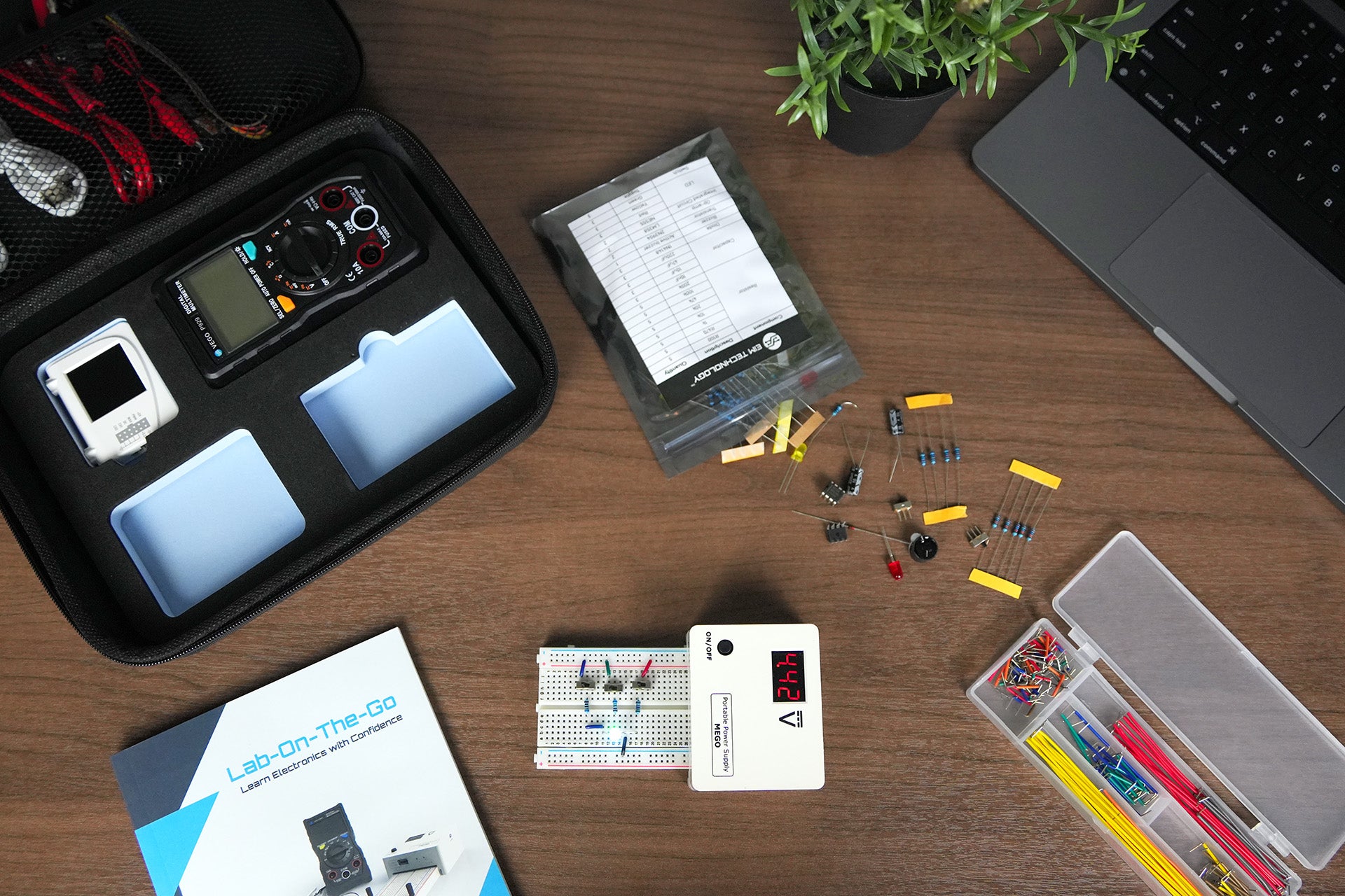
EIM Technology aims to provide tangible and effective learning solutions to all the engineering or electronics students, hobbyist and enthusiast out there. Check our DIY electronics learning kit with tutorial book, projects and accessories making it complete electronics kit at https://www.eimtechnology.com/collections/all-products