Imagine you want to use the AC (alternating current) power from your wall outlet to charge a battery. If the current is moving one way and delivers charge to the battery, once it starts going the other way, all of that charge is pulled back out, so no progress is ever made. We need the current to only flow in one direction. In other words, we need a DC (direct current) source. But if the power delivered to our homes is AC, how do we ever get the DC power needed to run most electronics? The answer is a rectifier, which allows us to turn AC power into DC power!
To do this, we need to allow current to flow in one direction, but block it when it tries to go in the other direction. This is precisely what a diode is for.
Diode Review
A diode is a component that only conducts current when it is forward-biased. It blocks the current when it is reverse-biased. An ideal diode would be forward-biased when the voltage across it is greater than zero and reverse-biased for any voltage less than zero. Real diodes, however, only become forward-biased once they reach some minimum positive voltage, often referred to as the forward voltage. This value is typically around 0.6 V for general-purpose diodes. The circuit symbol for a diode is shown below.

To summarize, a diode will allow current to pass when the voltage is greater than around 0.6 V. Any less than that, including negative values, and the current will be blocked.
Rectifier circuits
Half-Wave Rectifier
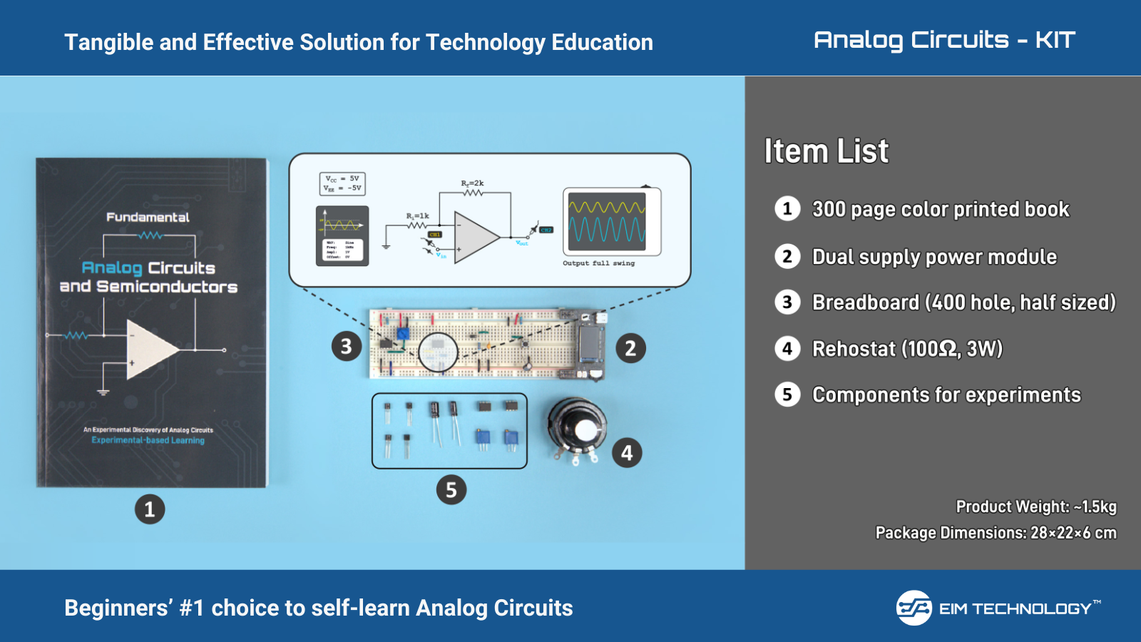
Let’s see what happens when we connect a resistor and a diode in series and give it a sinusoidal AC input using the Zoolark’s function generator. The resistor represents the output load. Here’s the schematic:

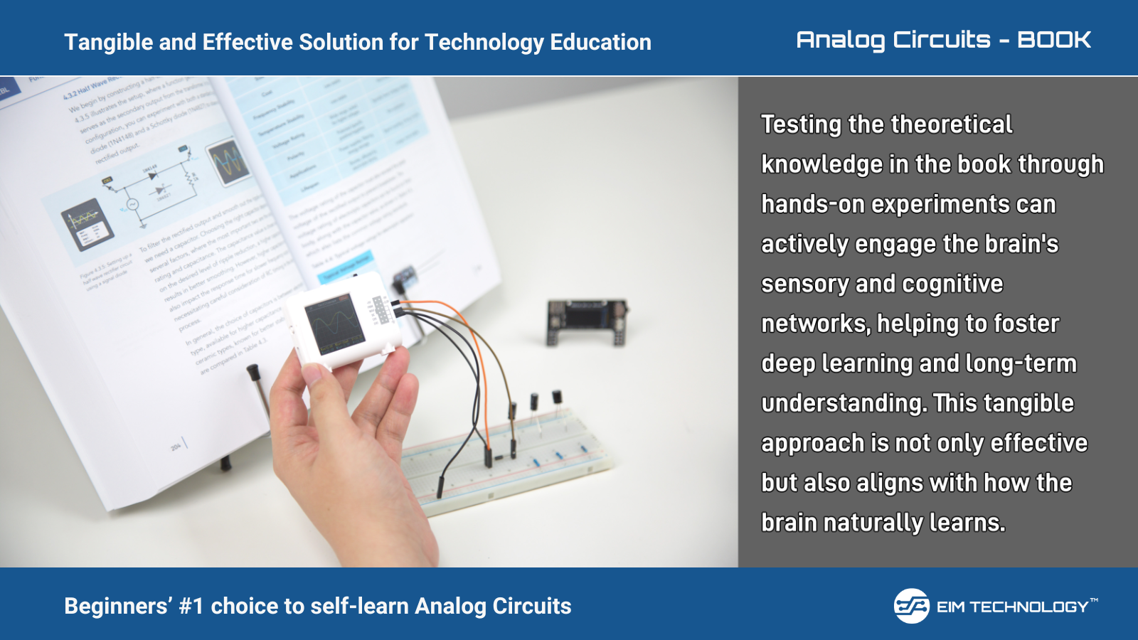
And now let’s put it together on a breadboard. I am using a 1 kΩ resistor for the load.

We will use the Zoolark’s oscilloscope to measure the load resistor.

We get a sine wave without the negative portions! This would allow us to charge a battery as the voltage is always either positive or zero, so the current is only flowing in one direction. This is great, but you might be thinking: aren’t we wasting power by only capturing half of the original sine wave? The answer is yes. This is why this type of rectifier is called the half-wave rectifier. It is the simplest to make, but not the most efficient.
Full-Wave Bridge Rectifier
Using a clever arrangement of diodes, we can capture both the positive and negative halves of the cycle. Take a look at the following schematic:

During the positive half of the signal, current flows through diode 2, through the resistor, and then through diode 3 and returns to the source. During the negative half, current flows through diode 4, through the resistor, and then through diode 1 and returns to the source. Notice that regardless of which half of the cycle we are in, current flows through the resistor from right to left. This means the current flowing through our load (the resistor) is always in the same direction!
Let’s add a few more diodes and see what this circuit looks like on our breadboard.

Now, I want to view the wave at the output on an oscilloscope, but unfortunately, this is a special case where I can’t use the Zoolark as both the function generator and oscilloscope because I would need different ground connections for each. I am lucky enough to have an extra Zoolark on hand, so I can use one for each, but if you’re following along with just one, you’ll have to take my word for it.
We will connect the oscilloscope across the load resistor.


Now, the entire wave is rectified! If you’re a math person, you may notice that this circuit performs the absolute value function. Our input is sin(t), and the output is |sin(t)|. Pretty cool, right? The unique-looking configuration of diodes used in this circuit is called a bridge, thus, the circuit as a whole is called the full-wave bridge rectifier.
Smoothing It Out With a Capacitor
Even with the full wave rectified, this output still doesn’t give us a constant DC voltage. It varies between the peak voltage and zero periodically, never giving a steady voltage value. We can improve our rectifier by putting a capacitor in parallel with the load resistor. Capacitors resist changes in voltage. In other words, it takes time for the voltage across the capacitor to change. This will smooth out the voltage, making it better resemble a constant DC voltage.


Let’s look at how our output is affected.

The yellow line (Channel 1) is our output. We now have a DC voltage that is nearly constant, varying between 2.2 and 2.4 V.