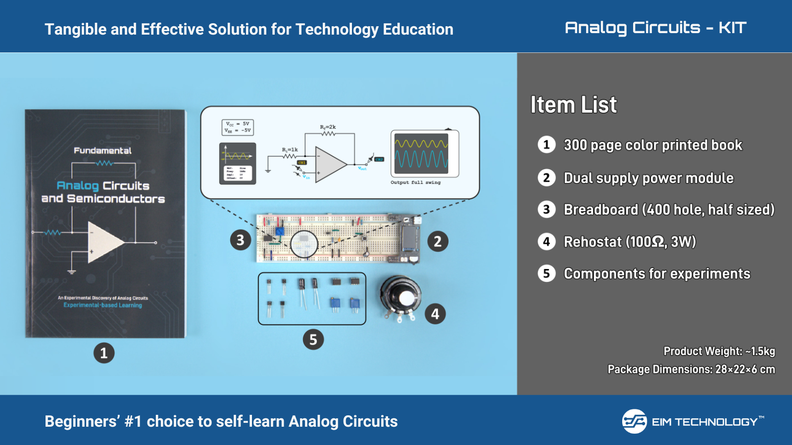
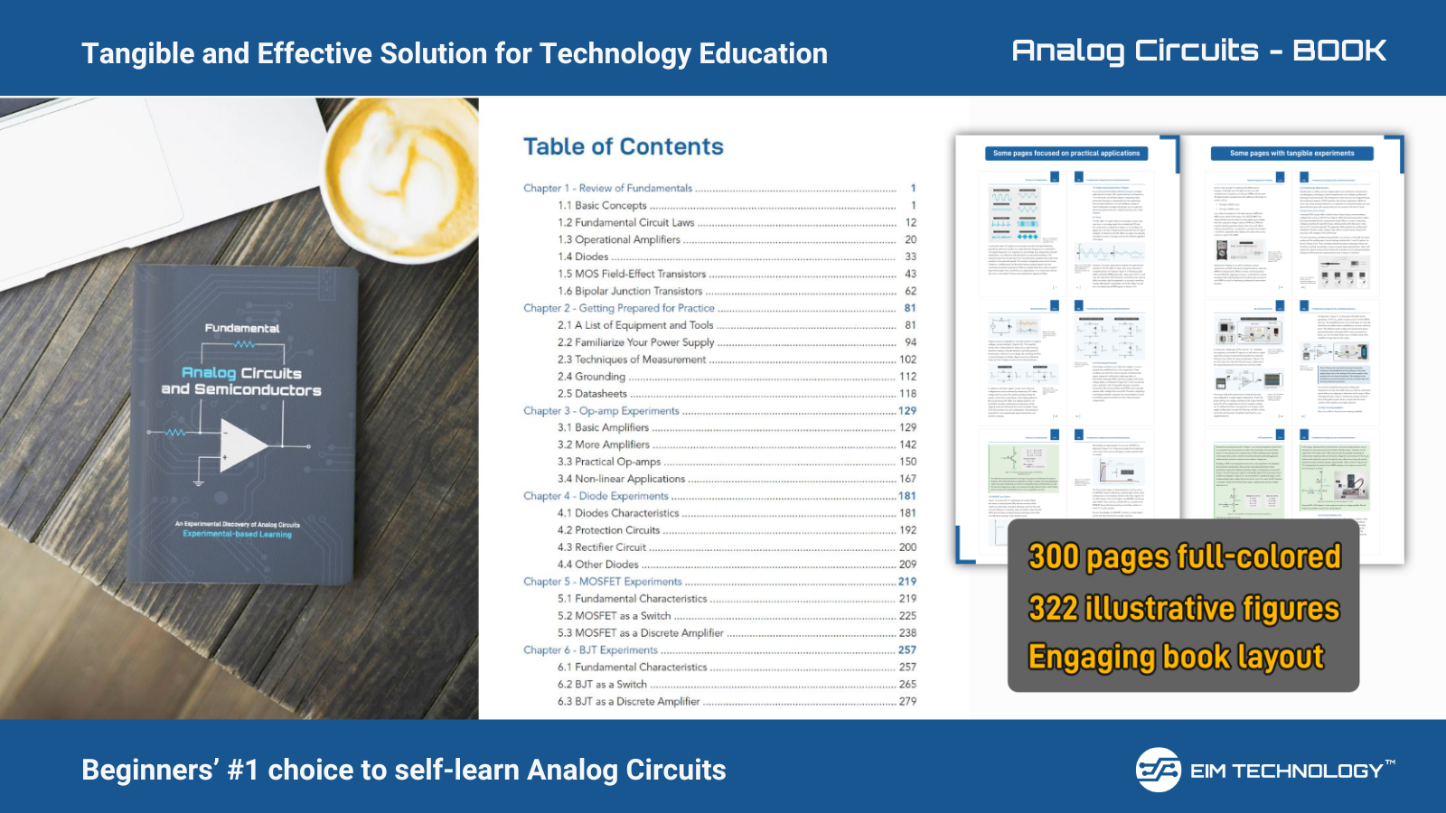
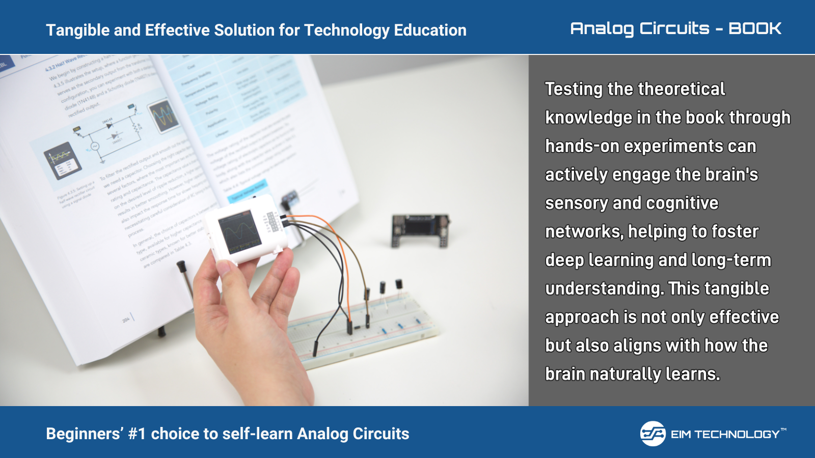
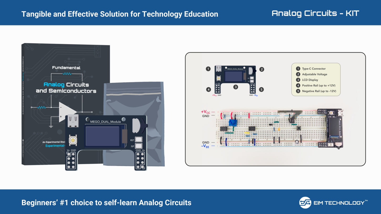
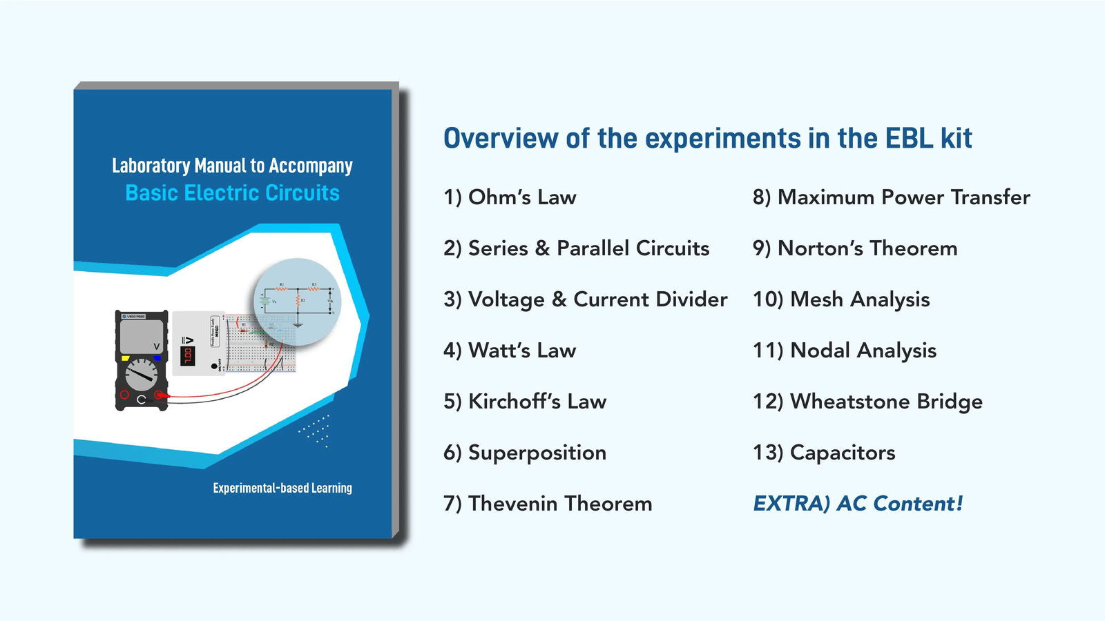
TIMER IC 555

555 Pin Diagram

Pin Configuration of 555 Timer with description:
|
PIN |
NAME OF THE PIN |
FUNCTION |
|
1 |
GROUND / GND |
Ground reference voltage, low level voltage (0V). |
|
2 |
TRIGGER / TRIG |
Triggers the internal flip-flop with a negative pulse that causes the output switching from low to high when Vtrig drops below 1/3 VCC. |
|
3 |
OUTPUT / OUT |
Drives any TTL circuit and can source or sink up to 200mA of current with an output voltage of approximately VCC-1.5V. |
|
4 |
RESET |
Resets the internal flip-flop and controls the state of the output on pin 3. Typically connected to a logic "1" level when not in use. |
|
5 |
CONTROL / CTRL |
Controls the timing of the 555 timer by varying the width of the output signal independently of the RC timing network. Connected to ground through a 10nF capacitor when not in use. |
|
6 |
THRESHOLD / THR |
Resets the flip-flop by causing the output to switch from high to low when the voltage applied to it exceeds 2/3Vcc. Connects directly to the RC timing circuit. |
|
7 |
DISCHARGE / DIS |
Discharges the timing capacitor to ground through an internal. Connects to ground when output is low |
|
8 |
Vcc / V+ SUPPLY |
Supplies power, typically between 4.5V and 15V for general purpose TTL 555 timers. |
Let us look back on time about Timer IC 555 (source: Wikipedia):
Who invented the 555 timer?
Hans R. Camenzind (Swiss Standard German: [ˈkaːməntsɪnd]; 1 January 1934 – 8 August 2012) was an electronics engineer known for designing the 555 timer IC. Hans R. Camenzind was working under Signets on contract.
The first design for the 555 was reviewed in the year 1971. After the closing an error-free design, Camenzind got the idea of using a direct resistance instead of a constant current source, finding that it worked satisfactorily. The design change decreased the required 9 external pins to 8, so the IC could be fit in an 8-pin package instead of a 14-pin package. This design change reduced the number of required external pins from 9 to 8, allowing the IC to fit into an 8-pin package instead of a 14-pin package. This revised version passed a second design review, and prototypes were completed in October 1971 as the NE555V (plastic DIP) and SE555T (metal TO-5). By 1972, the 555 timer was being manufactured by 12 companies and became a best-selling product. The 555 found many applications beyond timers.
Camenzind said "nine out of 10 of its applications were in areas and ways I had never contemplated. For months I was inundated by phone calls from engineers who had new ideas for using the device."
Why 555 timer is called 555?
Several books report the name "555" timer IC derived from the three 5 kΩ resistors inside the chip. there are three 5kΩ resistors connected together internally producing a voltage divider network between the supply voltage at pin 8 and ground at pin 1.
Hope you find the explanation of the timer IC 555 and were able to learn about the history of the IC
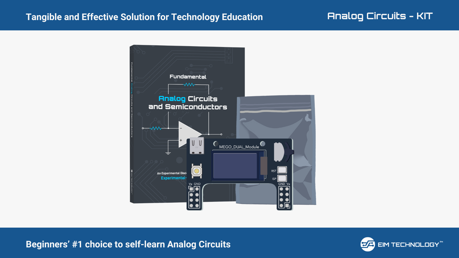
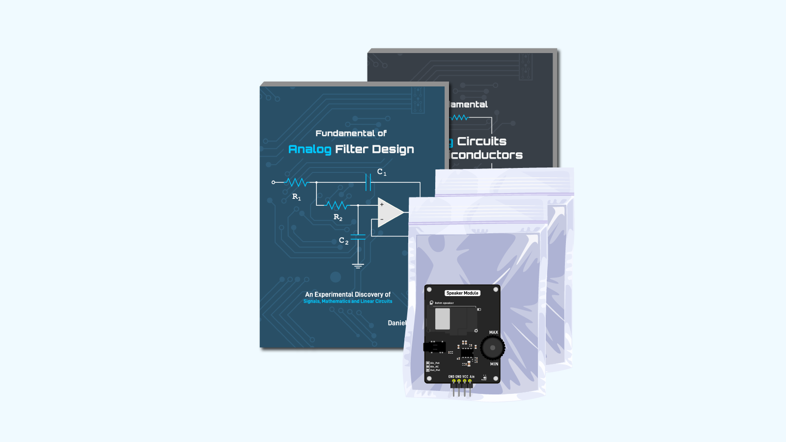
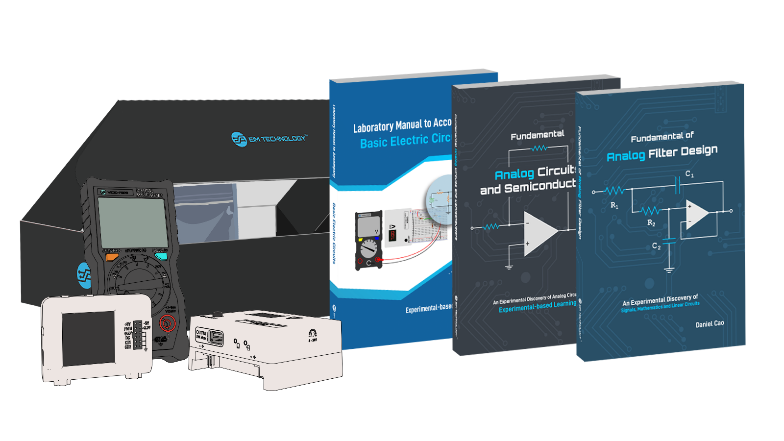
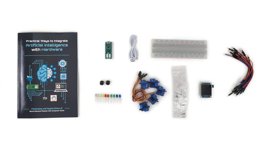
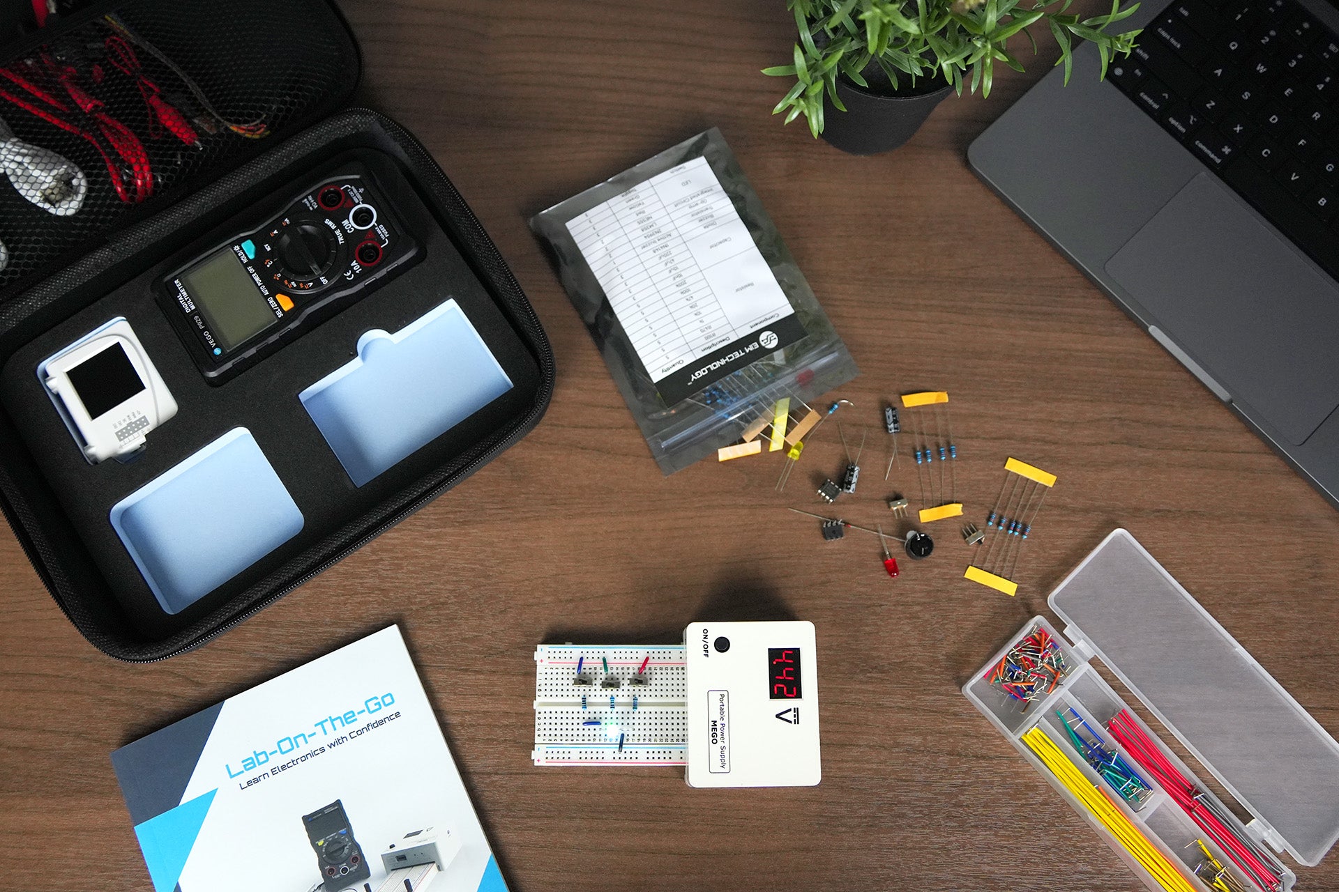
You can learn about theory and practical applications of IC 555 in our Lab-On-The-Go kit where we have summarized the timer IC and put together experiments like Flashing LED with 555 Timer. Check our YouTube video here > https://www.youtube.com/watch?v=bMF4enQnaF0
We will be discussing the 555 timer IC block diagram and 555 timer internal circuit diagram in the next blog.
Comment you feedback on the blog and follow us for more blog updates.