KCL and KVL
Kirchhoff's Laws are two fundamental principles used to analyze electrical circuits, named after Gustav Kirchhoff, a German physicist. The two laws are:
- Kirchhoff's Current Law (KCL): It states that the total current flowing into a junction (or node) in an electrical circuit is equal to the total current flowing out of that junction. In other words, the algebraic sum of currents at any junction in a circuit is zero.
- Kirchhoff's Voltage Law (KVL): It states that the sum of the electromotive forces (EMFs) and voltage drops around any closed loop in a circuit is equal to zero. In simpler terms, the sum of the voltages across all elements (such as resistors, capacitors, and inductors) in a closed loop is equal to the total voltage supplied by the sources in that loop.
Kirchhoff's laws are essential tools for analyzing and solving complex electrical circuits. They are based on the principles of conservation of charge (KCL) and conservation of energy (KVL), and they form the foundation of circuit analysis techniques. By applying Kirchhoff's laws, engineers can determine currents, voltages, and power distributions within circuits, enabling the design and troubleshooting of electronic systems.
Kirchhoff’s Current Law
Kirchhoff's Current Law (KCL) is a fundamental principle in electrical engineering and physics. It states that at any node (junction) in an electrical circuit, the sum of currents entering the node equals the sum of currents leaving the node. In other words, the algebraic sum of currents entering a node is zero.
Mathematically, KCL can be expressed as:
ΣI_in = ΣI_out
Where:
- ΣI_in is the sum of currents entering the node.
- ΣI_out is the sum of currents leaving the node.
It is important to first understand the concept of nodes in a circuit. When more than two elements are connected at a point, this point is called a node. In Figure 5.1 we labeled points a, b and c, but b is the only node since it is attached to three elements. The bottom point is also a node but more often referred as a ground.

Figure 5.1: Electrical node of a circuit
Kirchhoff’s Current Law, or KCL states that the net current of a node is always equals to 0. On the circuit diagram it means at node b the algebraic sum of I1, I2 and I3 is zero.
At node b: I1 + (-I2) + I3 = 0
The three currents on the diagram are arbitrarily assigned, and from the equation we noticed currents can be positive or negative, this is only to do with the definition of current directions. For example, if we set current flowing into the node as positive, then I2 will be negative since it is flowing out. If I2 was drawn on the opposite direction, then we put a positive sign as well.
Kirchhoff’s Voltage Law
Kirchhoff's Voltage Law (KVL) is one of the fundamental principles used in electrical circuit analysis. It states that the sum of the voltages around any closed loop in a circuit is equal to zero. In other words, the algebraic sum of the voltage rises and voltage drops encountered as you traverse a closed loop in a circuit is zero.
Mathematically, KVL can be expressed as:
ΣV = 0
Where:
- ΣV is the sum of the voltages around the closed loop.
- This sum includes both voltage sources (emf) and voltage drops across passive elements like resistors, capacitors, and inductors.
KVL is based on the principle of conservation of energy, which states that energy cannot be created or destroyed, only transformed from one form to another. Therefore, the total energy input into a closed loop in a circuit (represented by voltage sources) must be equal to the total energy consumed (represented by voltage drops across circuit elements).
To apply Kirchhoff’s Voltage Law (KVL), we need to understand the definition of a loop, which is defined as a closed path in a circuit. The circuit drawn in Figure 5.2 has three loops.

Figure 5.2: The loops in a circuit
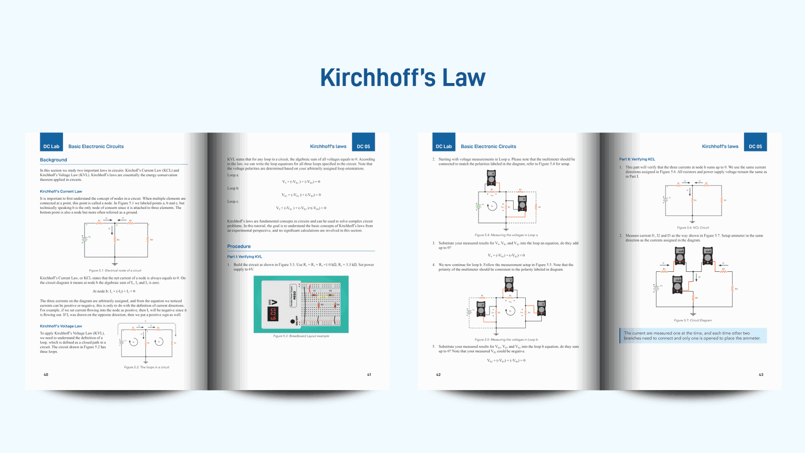
KVL states that for any loop in a circuit, the algebraic sum of all voltages equals to 0. According to the law, we can write the loop equations for all three loops specified in the circuit. Note that the voltage polarities are determined based on your arbitrarily assigned loop orientations.
Loop a:
VS + (-VR1) + (-VR2) = 0
Loop b:
VR2 + (-VR3) + (-VR4) = 0
Loop c:
VS + (-VR1) + (-VR3) + (-VR4) = 0
Kirchhoff’s laws are fundamental concepts in circuits and can be used to solve complex circuit problems. In this tutorial, the goal is to understand the basic concepts of Kirchhoff’s laws from an experimental perspective, and no significant calculations are involved in this section.
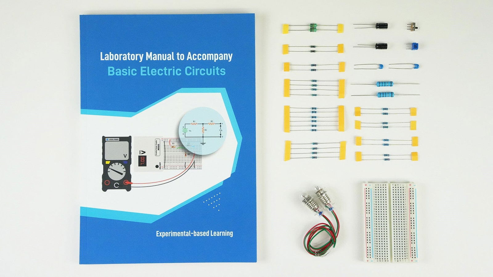
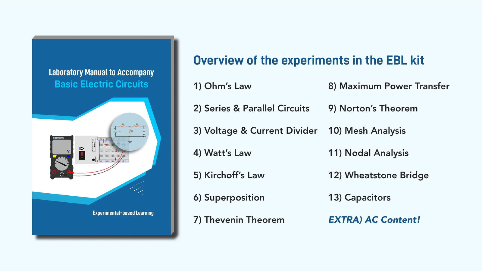
EIM TECHNOLOGY’s Experiment Based Learning Kit – Basic Electrical Circuits

Now, we know the theory, with our Electrical Circuits Learning Kit we bring the balance of theory and practical learning.