Operational Amplifier are most efficient and loved analog device amongst the engineers. Simply because the features it offers and flexibility to use in it different configurations. One of the striking one could its closed loop feedback configuration, allowing for precise control over its gain and behavior.
An inverting amplifier uses negative feedback, where a portion of the output signal is fed back to the inverting (-) input of the op-amp through a feedback resistor (Rƒ). This feedback forces the differential input voltage to approach zero, creating a closed-loop circuit.
Inverting Op-amp Amplifiers / Inverting Operational Amplifiers Circuit
In an inverting amplifier circuit, feedback is used to create closed-loop operation. Two important rules to remember are:
-
No current flows into the input terminals.
-
V1 (voltage at the inverting input) always equals V2 (voltage at the non-inverting input).

In this setup:
- The amplifier’s gain is now controlled and is called the closed-loop gain, though it’s lower than the open-loop gain.
- The inverting input terminal receives a combination of the input signal and feedback, making it a summing point. An input resistor (Rin) is used to separate the actual input signal from this point.
- The non-inverting (+) input is grounded, creating a condition called virtual earth, meaning the inverting input is effectively at zero volts.
Overall, this circuit ensures that the output is a scaled and inverted version of the input signal, behaving as a differential amplifier.

However, in real-world op-amp circuits, these rules are slightly violated. The junction (X) where the input and feedback signals meet is at the same potential as the non-inverting input, which is at zero volts (ground), creating a "virtual earth." This means the inverting input is almost at ground potential, even though no actual current flows into the input.
Key points:
- The input resistance of the amplifier is equal to the input resistor (Rin).
- The closed-loop gain of the inverting amplifier is determined by the ratio of the feedback resistor (Rƒ) to the input resistor (Rin).
Using the two rules (no current into input terminals and V1 = V2 = 0), you can derive the equation for the amplifier's gain by analyzing the current through the resistor network. The circuit’s closed-loop gain is:
![]()
This means the output is inverted and scaled by the ratio of the two resistors.
Simple Inverting Op-amp Circuit

Inverting Op-amp Formula:


The negative sign in the inverting amplifier's gain equation indicates that the output signal is inverted, meaning it is 180° out of phase with the input signal. This happens because of the negative feedback applied to the circuit.
Inverting Op-amp Amplifier Output Waveform and Analysis of the Inverting Amplifier Formula

This above summarized equations shows that the circuit is linear, meaning the output voltage is directly proportional to the input voltage, with the proportionality defined by the gain. This linearity makes the inverting amplifier useful for amplifying small sensor signals, converting them into larger voltages while maintaining the same signal characteristics, except for the phase inversion.
For an inverting amplifier, the multiplier (which is the closed loop voltage gain) can be precisely controlled by choosing the feedback resistor Rf and input resistor Ri. This configuration offers a simple way to control amplification. Additionally, the output signal (Vout) is inverted to the input (Vin). In other words, a sine wave input will result in a cosine wave output.
Inverting Op-amp Amplifier Problem:

Where to learn about an Op-amp Amplifier ?
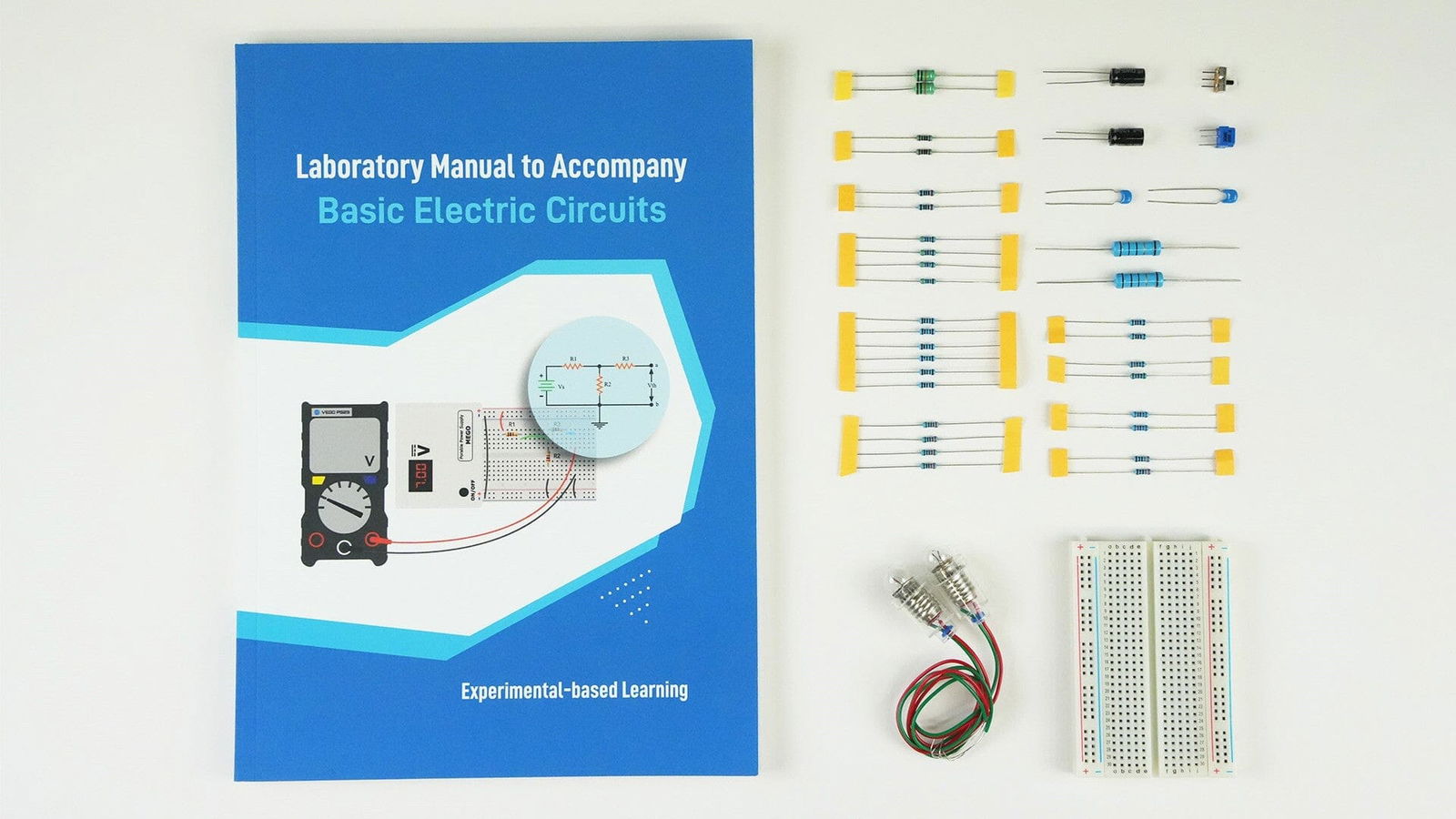
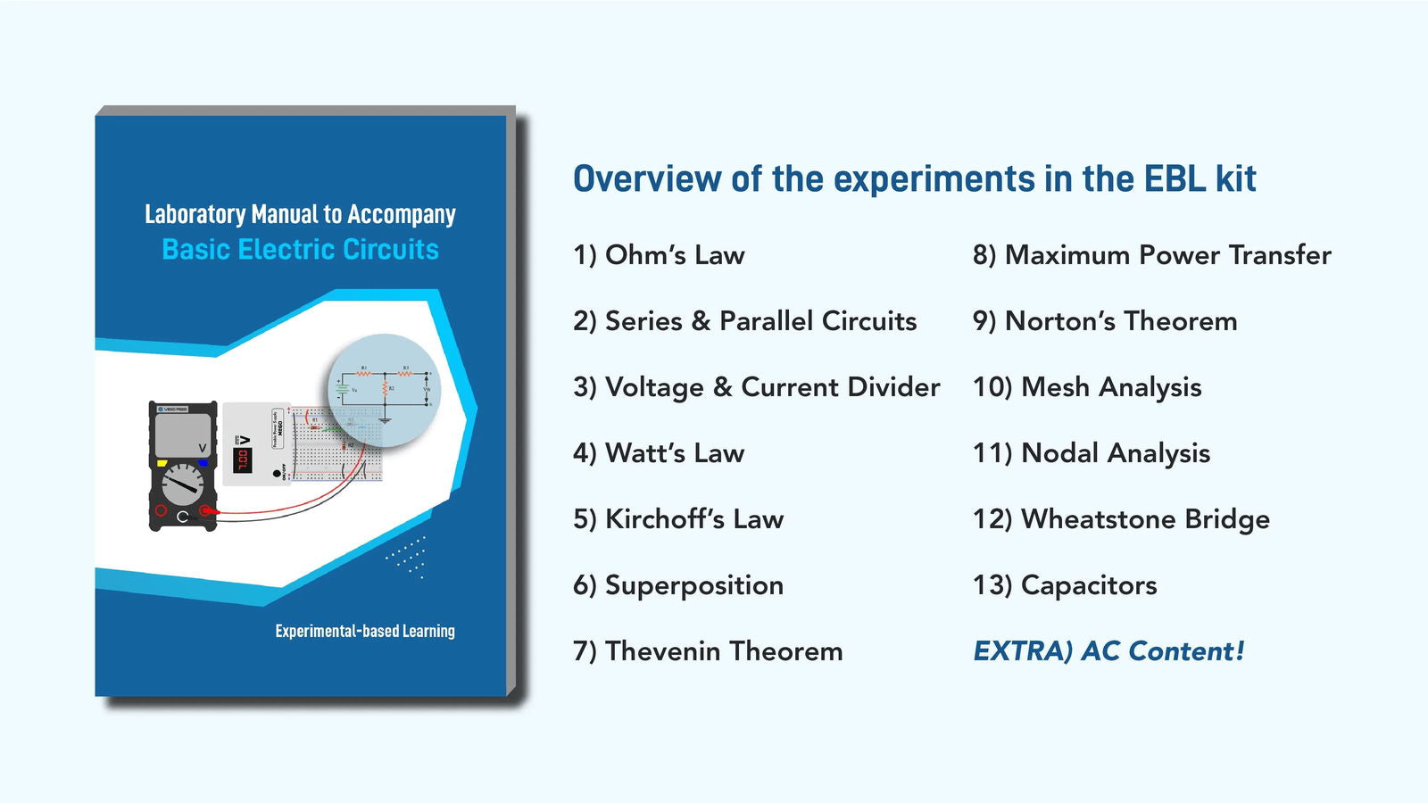
Check our Fundamental of Analog Circuits and Semiconductors Learning Kit
https://www.eimtechnology.com/products/fundamental-analog-circuits-semiconductors