In general terms, an operational amplifier (Op-Amp) is an integrated circuit that can amplify voltage. Let us look at what is an op-amp or operational amplifier, what is the op-amp layout, what are the characteristics of an ideal op-amp, know the pin configuration of LM 741 op-amp IC, and find out a perfect self-learning tutorial guide to learn about op-amp circuits in practical.
What is an ideal Op-Amp?
The ideal op amp is an amplifier with infinite input impedance, infinite open-loop gain, zero output impedance, infinite bandwidth, and zero noise. It has positive and negative inputs which allow circuits that use feedback to achieve a wide range of functions.

Figure: operational amplifier layout
Equivalent Circuit of an Ideal Op-amp - Operational Amplifier

The equivalent circuit is useful in analyzing the basic operating principles of op-amps and in observing the effects of feedback arrangements. From the above figure we can say that the output voltage is
Vo = A Vid = A (V1-V2) ……………………. equation 1
where A = large-signal voltage gain
Vid = difference input voltage
V1 = voltage at the non-inverting terminal with respect to the ground
V2 = voltage at the inverting terminal with respect to the ground
The equation 1 indicates that the output voltage Vo is directly proportional to the algebraic difference between the two input voltage and it does not amplify the input voltage themselves. For this reason, the polarity of the output voltage depends on the polarity of the difference voltage.
Characteristics of an Ideal Op-Amp & Parameters
Ideal Op-amp have below characteristics. Let us see how some of the op-amp characteristic is crucial and what results we gain with them.
- Open Loop Gain (Avo) - ∞
- Infinite: The primary function of an operational amplifier (op-amp) is to amplify the input signal. Ideally, the open-loop gain (the gain without any positive or negative feedback) would be infinite. In reality, typical op-amps have open-loop gains ranging from approximately 20,000 to 200,000.
- Input Impedance (Zin) - ∞
- Infinite: The input impedance of an ideal op-amp is assumed to be infinite, which means no current flows from the source into the op-amp's input circuitry (IIN = 0). Real op-amps exhibit input leakage currents ranging from a few picoamps to several milliamps.
- Output Impedance (Vout) - 0
- Zero: An ideal op-amp has zero output impedance, acting as a perfect internal voltage source without internal resistance. This allows it to supply as much current as necessary to the load without any voltage drop. In practice, real op-amps have output impedances between 100Ω and 20kΩ.
- Bandwidth (BW) - ∞
- Infinite: An ideal op-amp would have an infinite frequency response, capable of amplifying signals from DC to the highest AC frequencies, thus having infinite bandwidth. However, real op-amps are limited by the Gain-Bandwidth product (GB), which defines the frequency at which the amplifier's gain drops to unity.
- Offset Voltage (Vin) - 0
- Zero: Ideally, the output voltage of an op-amp would be zero when the voltage difference between the inverting and non-inverting inputs is zero. Real op-amps, however, have some amount of output offset voltage.
From these characteristics of an ideal op amp, we observe that:
- The input impedance is infinite, meaning no current flows into either input terminal (the "current rule").
- The differential input offset voltage is zero (the "voltage rule").
These properties are essential for understanding the analysis and design of op-amp circuits.
LM 741 Op-amp Pin Layout and Description
Below is the pin diagram and description for a commonly used op-amp, such as the 741 op-amp:
- PIN 1: Offset Null (Offset N1): This pin is used for offset voltage nulling. It is connected to one end of a potentiometer (the other end of the potentiometer is connected to pin 5).
- PIN 2: Inverting Input (V- or Inverting Input): This is the input where the signal that you want to invert is applied.
- PIN 3: Non-Inverting Input (V+ or Non-Inverting Input): This is the input where the signal that you want to amplify is applied without inversion.
- PIN 4: Negative Power Supply (V- or Vss): This pin is connected to the negative supply voltage. In dual power supply configurations, this would be connected to the negative voltage. For single-supply configurations, it is usually connected to ground.
- PIN 5: Offset Null (Offset N2): This pin is used for offset voltage nulling, similar to pin 1.
- PIN 6: Output: This is the output of the op-amp where the amplified signal is available.
- PIN 7: Positive Power Supply (V+ or Vdd): This pin is connected to the positive supply voltage.
- PIN 8: No Connection (NC): This pin is not connected to any circuitry inside the op-amp.
Learning Op-amp Circuits
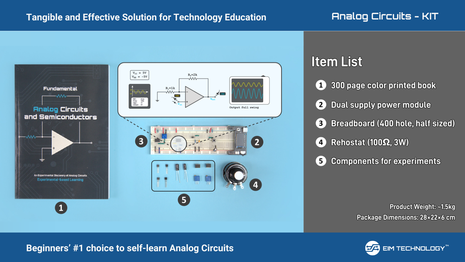
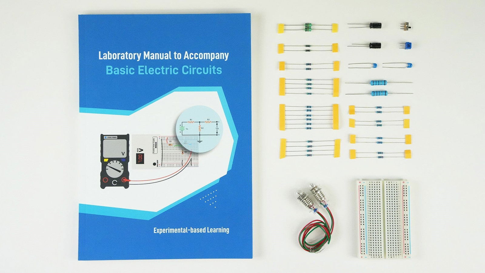
Learn Op-amp Theory & practical with our tutorial book + learning kit: Fundamental of Analog Circuits and Semiconductors.
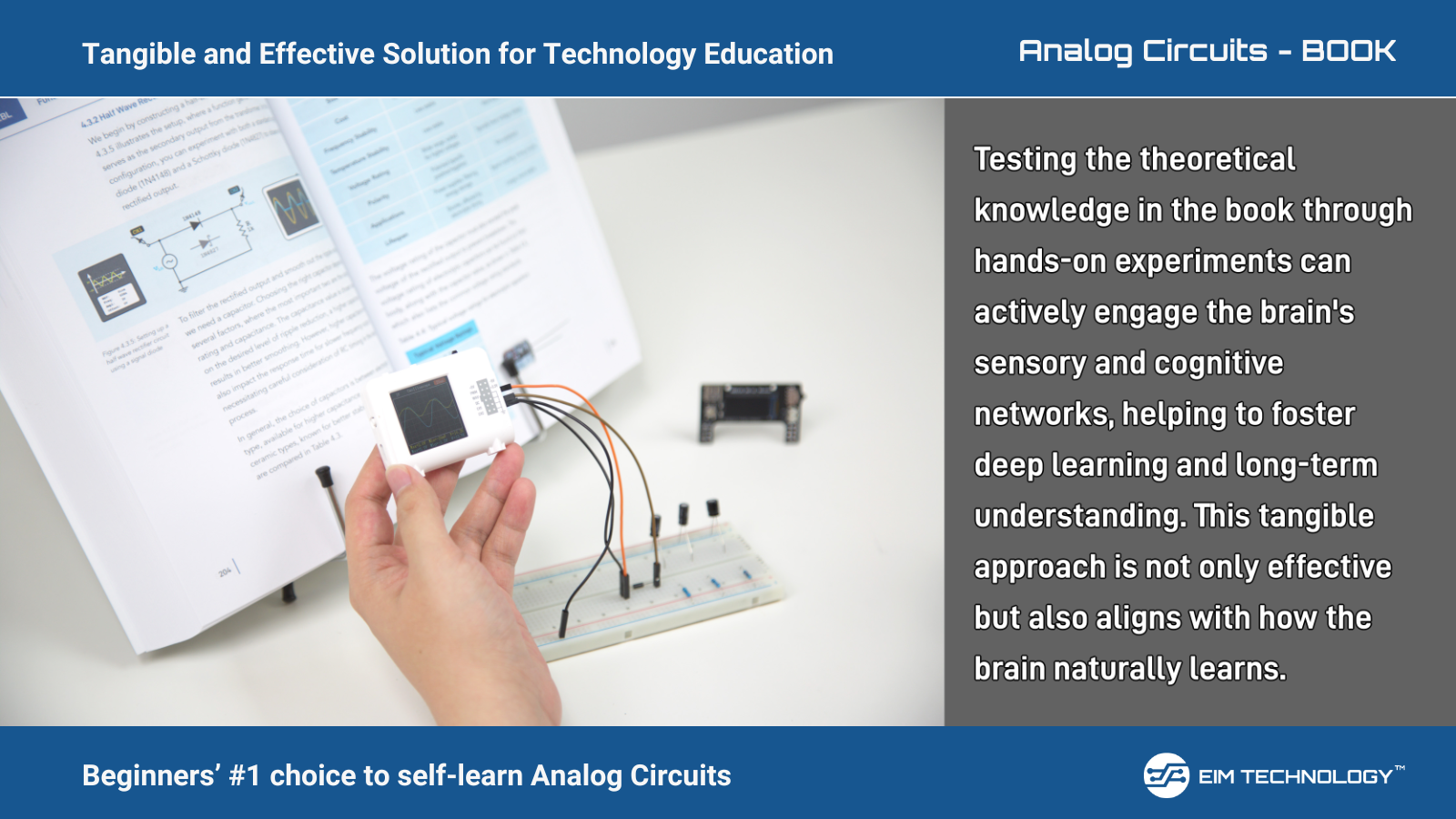
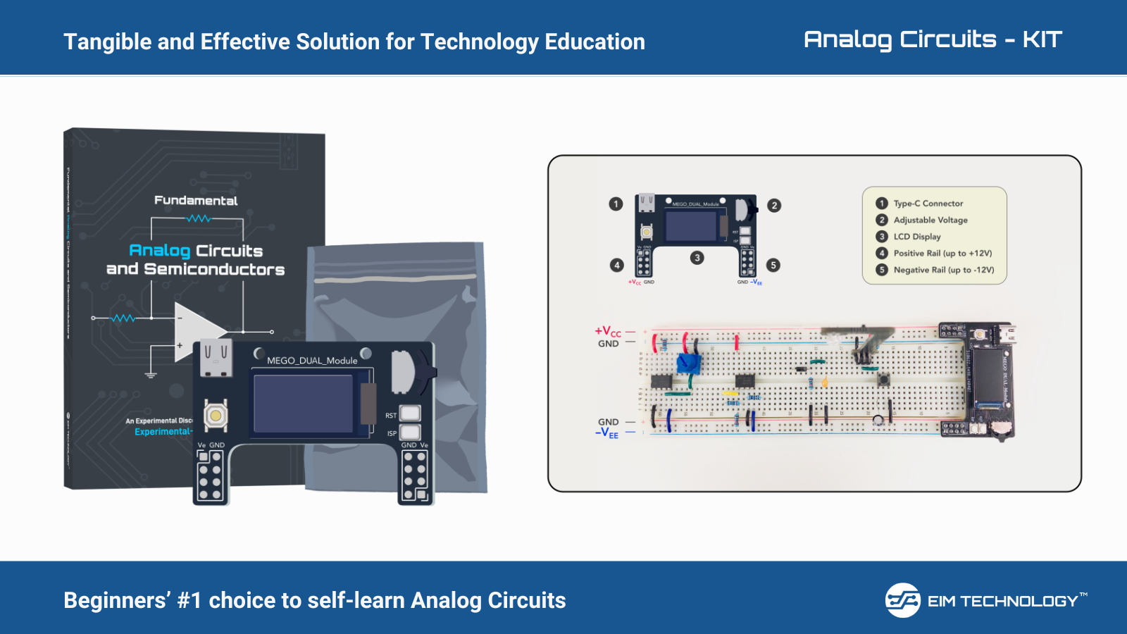
Check our Fundamental of Analog Circuits and Semiconductors tutorial book and analog circuits learning kit that comes theory explanation with practical applications of the analog devices and circuits. We will be coming up with a blog where we discuss Op-Amp’s internal circuitry and what is an ideal Op-Amp.

Figure: Fundamental of Analog Circuits and Semiconductors tutorial book + Learning kit
Check our Fundamental of Analog Circuits and Semiconductors tutorial book and analog circuits learning kit that comes theory explanation with practical applications of the analog devices and circuits.
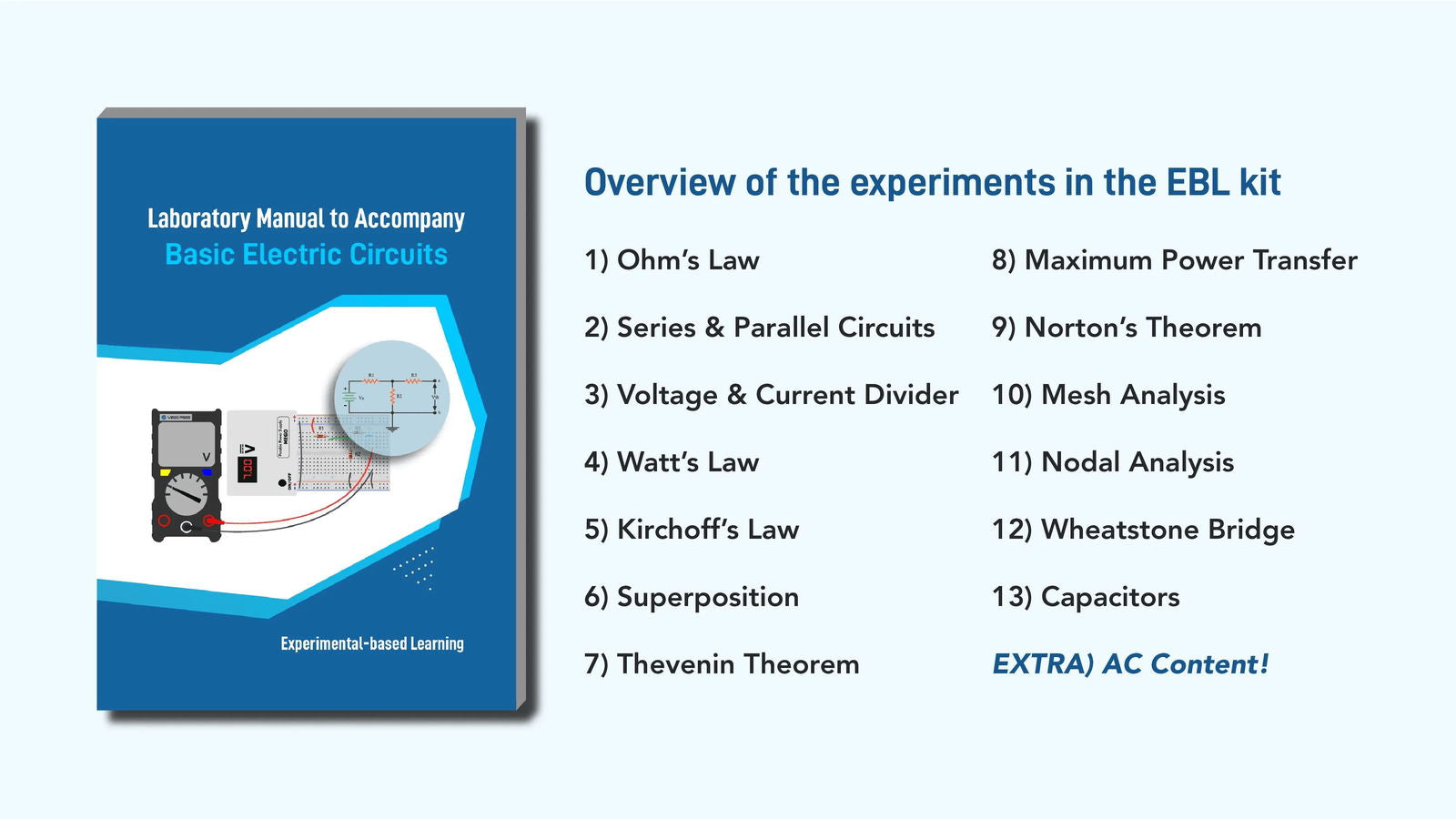
Overview of the Chapter: Op-amps
- Dive into op-amp experiments, to get exposure to the op amp circuit or
operational amplifier circuits - Starts with basic amplifiers and progresses to advanced configurations
- Explores practical op-amp applications and non-linear experiments
- Includes 4 big sections with 16 sessions of topics

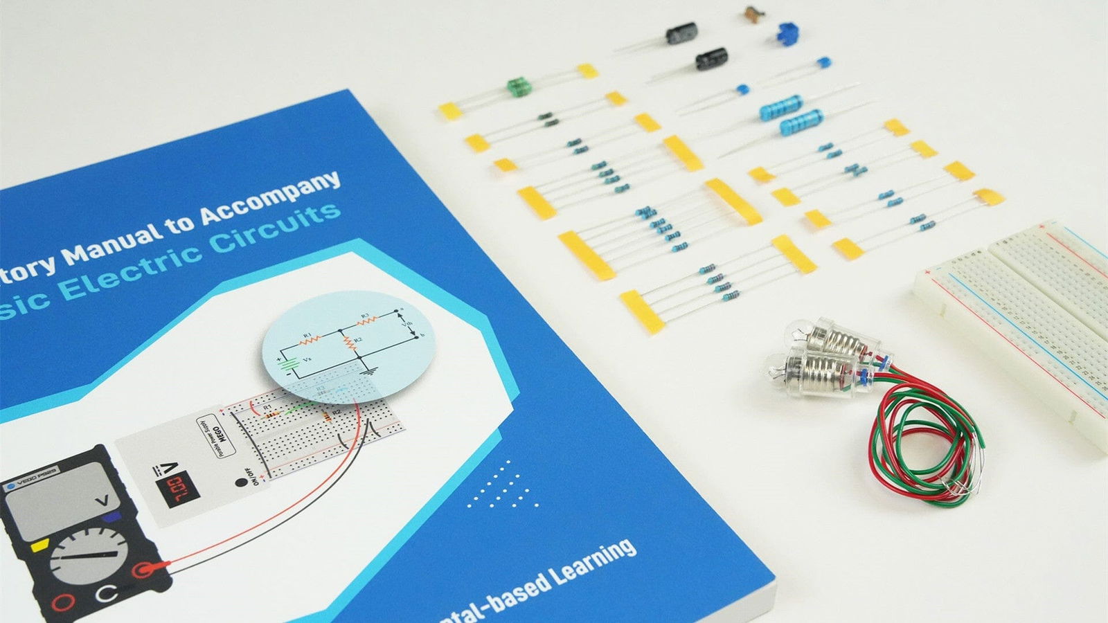
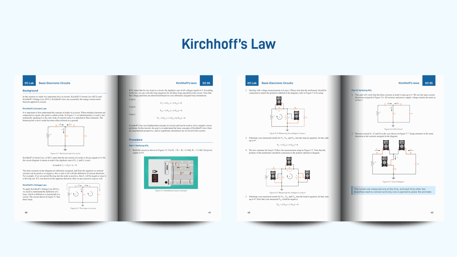
Figure: Preview of Fundamental of Analog Circuits and Semiconductors tutorial book + Learning kit
Check the Analog Circuit tutorial at - https://www.eimtechnology.com/collections/all-products/products/fundamental-analog-circuits-semiconductors
We have already received overwhelming response before pre-launch of the entire kit by users pre-ordering the Fundamental of Analog Circuits and Semiconductors.
You can too pre-order the learning kit and get 20% OFF instantly – Use link >> https://www.eimtechnology.com/discount/poanalog20?redirect=%2Fproducts%2Ffundamental-analog-circuits-semiconductors
Links:
Our website: www.eimtechnology.com
Our email: info@eimtechnology.com
Our Catalogue DIY Learning Kit: https://www.eimtechnology.com/collections/all-products
Subscribe to our emails to receive updates & offers.


