If you’ve spent any time making circuits on breadboards, you’ll know things can sometimes get messy, especially when your circuit is complex. There’s no worse feeling than finding a cool circuit online, wiring it up, and turning it on to find it doesn’t work. Often this is because of a subtle wiring error or backward component, but if your breadboard is messy, fixing it will feel like finding a needle in a haystack. In this article, we’re going to build an LED follower circuit using a 555 Timer and share some tips for how you can keep your circuit clean and easy to understand as you go along.
First, here’s the schematic for the circuit we are aiming to build.

Note: The transistors are NPN bipolar junction transistors. I am using the 2N3904 but the BC547 or any other general-purpose BJT will work just as well.
This circuit has an integrated circuit, the 555 Timer, so let’s put that on the board first, near the middle so that we have room to work on both sides.

The small wires you see are connecting all of the power rails together. Most breadboards have power rails that run the length of the board, but the one I’m using here actually has them separated at the midpoint.
Tip #1: Prioritize Large Components
The first step in making an organized circuit is to think ahead. Looking at the schematic, which components will take up the most space? We don’t want to put these in last and realize we have no space for them. Surely the LEDs and the transistors are going to the largest components, so let’s pick a spot for them and place them down first, along with the resistors connected to the LEDs.

Curious how my resistors and LEDs look so neat? This leads us to the most important tip in this article!
Tip #2: Cut Down Component Leads!
Once you figure out where you want to place a component, you can cut the leads down to just the necessary amount to make the connection. This will make your board much neater, and make it easier to see where components are connected.


I can make these components’ leads very short since they are connecting points that are right next to each other. We’ll see soon that we can’t make them all this short.
Next, let’s add R3, R4, and D1. We will trim down R4 in a similar fashion. R3 and D1, on the other hand, need to reach all the way to the IC. I’m going to place them in without trimming them to get an idea of how long they need to be.

Once I have bent them into the position you see above, I can take them out and cut them just a bit below where the lead bends. This means the component will reach where it needs to go on both ends but still sit snugly in the board.


We’ll do the same for C2 to complete this part of the circuit.
Next, we need to make a few simple connections between the 555 Timer and the power rails. Pins 4 and 8 connect to the positive rail and pin 1 connects to the ground. The way you do this is very important.
Tip #3: Avoid Jumper Wires, Make Your Own
Jumper wires (also called DuPont wires) are very convenient, but having a lot of them on your breadboard creates a huge mess. For example, here’s a breadboard I put together some time back using exclusively jumper wires.

Any idea what this circuit does? Yeah, didn’t think so. You can avoid this spaghetti nightmare by getting yourself some rolls of wire (preferably in various colours) and a pair of wire strippers. Note that you will want solid wire (instead of stranded wire) for breadboards.

This will allow you to make wires that are just the right length for your connections, making them much nicer on the eyes. Let’s add the necessary wires to our circuit.

Next, we’ll add R1, R2, and C1, following my earlier advice of cutting down the leads.

Finally, we need to connect pin 7 to the point between R1 and R2, and pin 2 and 6 to the point between R2 and C1, but not with just any wire.
Tip #4: Colour Code Your Wires
You may have noticed that I connected pins 4 and 8 to the positive rail using red wires, while I connected pin 1 to the ground using a black wire. That was intentional. By maintaining this convention, we can easily identify positive voltage connections and ground connections just by the colour of the wire. For this reason, the next few connections will not use red or black wires as they do not connect to a power rail. Instead, I will use a green wire to connect pin 7 and blue wires to connect pins 2 and 6. I am using blue for both 2 and 6 to indicate that they are making the same connection.

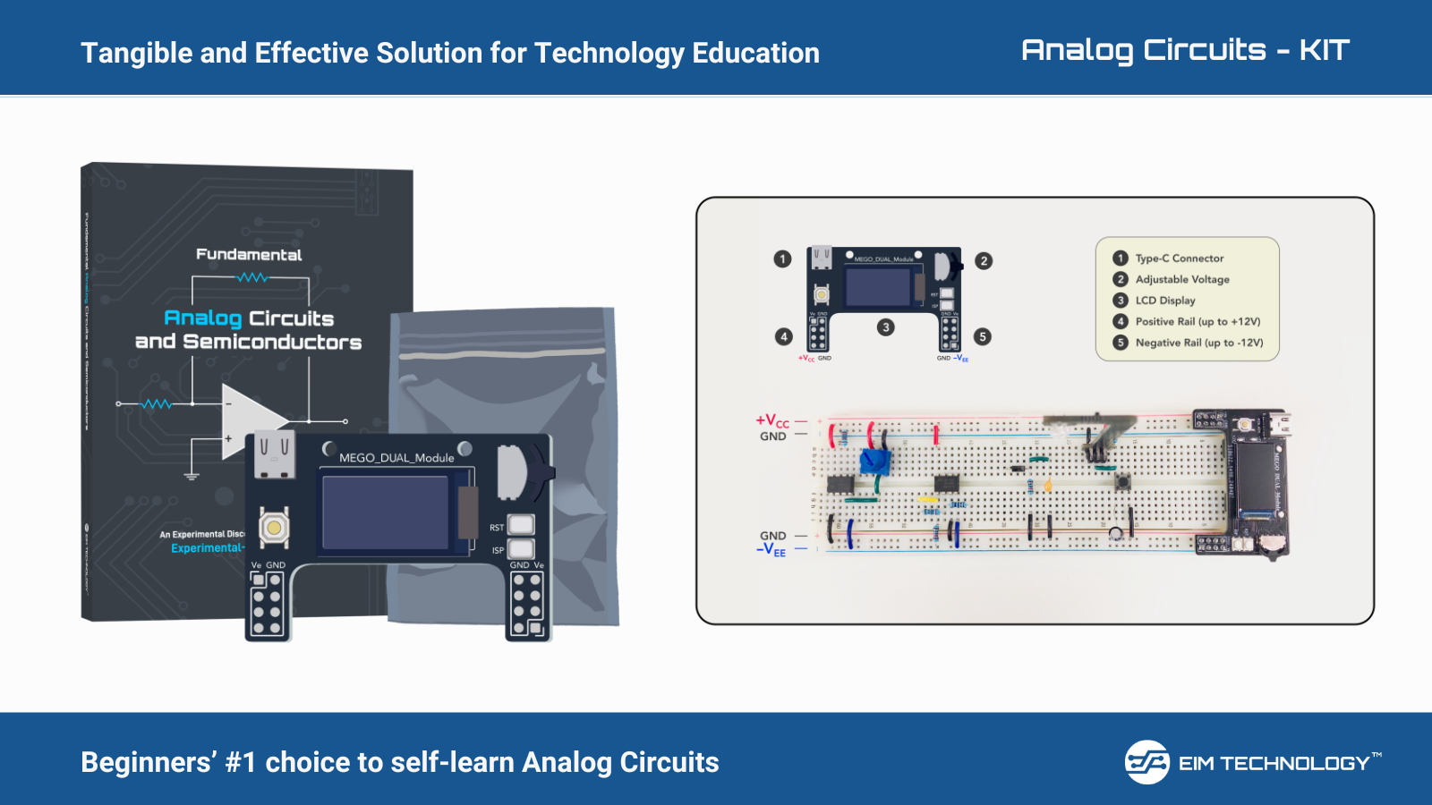
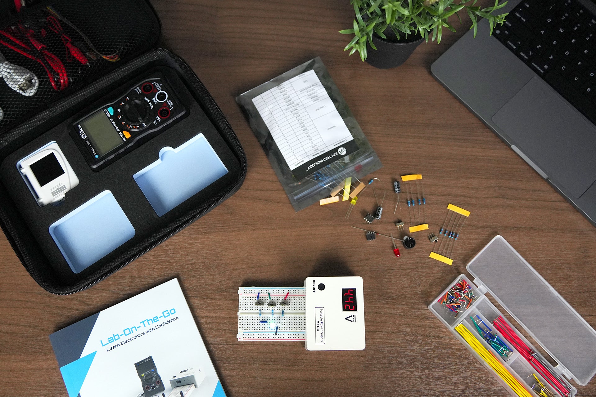
That should do it. Let’s set our MEGO power supply to 9 V and turn it on.

The LEDs light up in succession, moving from right to left and looping indefinitely. And most importantly, our board looks very tidy and professional.