555 Timer Circuit

The 555 timer is a widely used integrated circuit (IC) with applications in timing, pulse generation, and oscillator functions. Its internal structure is composed of several key components that work together to achieve its functionality.
1. Voltage Divider
The 555 Timer Circuit contains three 5kΩ resistors connected in series across the supply voltage (Vcc). This configuration divides the supply voltage into three equal parts, creating reference voltages of and . These reference voltages are critical for the operation of the internal comparators.
2. Comparators
- Comparator 1: This comparator in the 555 Timer Circuit compares the voltage at the threshold input (pin 6) with 2/3Vcc. When the threshold voltage exceeds 2/3Vcc, the output of Comparator 1 goes high.
- Comparator 2: This comparator compares the voltage at the trigger input (pin 2) with . When the trigger voltage drops below , the output of Comparator 2 goes high.
3. Flip-Flop
The outputs of the two comparators are connected to an SR (Set-Reset) flip-flop. The flip-flop controls the output of the 555 timer:
- When Comparator 2's output goes high, the flip-flop is set, causing the output (pin 3) to go high.
- When Comparator 1's output goes high, the flip-flop is reset, causing the output to go low.
4. Discharge Transistor
The discharge transistor in the 555 Timer Circuit is connected to the discharge pin (pin 7). It is controlled by the flip-flop and is used to discharge the external timing capacitor in astable or monostable mode. When the flip-flop is reset (output low), the transistor is turned on, discharging the capacitor. When the flip-flop is set (output high), the transistor is turned off, allowing the capacitor to charge.
5. Output Stage
The output stage of the 555 timer is an inverting buffer that can drive both high and low states on the output pin (pin 3). It is capable of sourcing or sinking current, allowing the IC to interface with various types of loads.
6. Control Voltage Pin
The control voltage pin (pin 5) provides access to the inverting input of Comparator 1. By applying an external voltage to this pin, the user can modify the 2/3Vcc threshold, thereby changing the timing characteristics of the circuit.
7. Reset Pin
The reset pin (pin 4) provides a direct method to reset the flip-flop, overriding all other inputs. When the reset pin is held low, the output (pin 3) is forced low, regardless of the conditions on the other pins. Normally, this pin is connected to Vcc for regular operation.
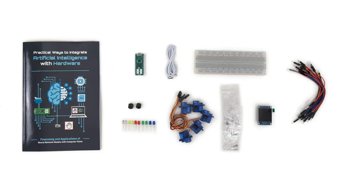
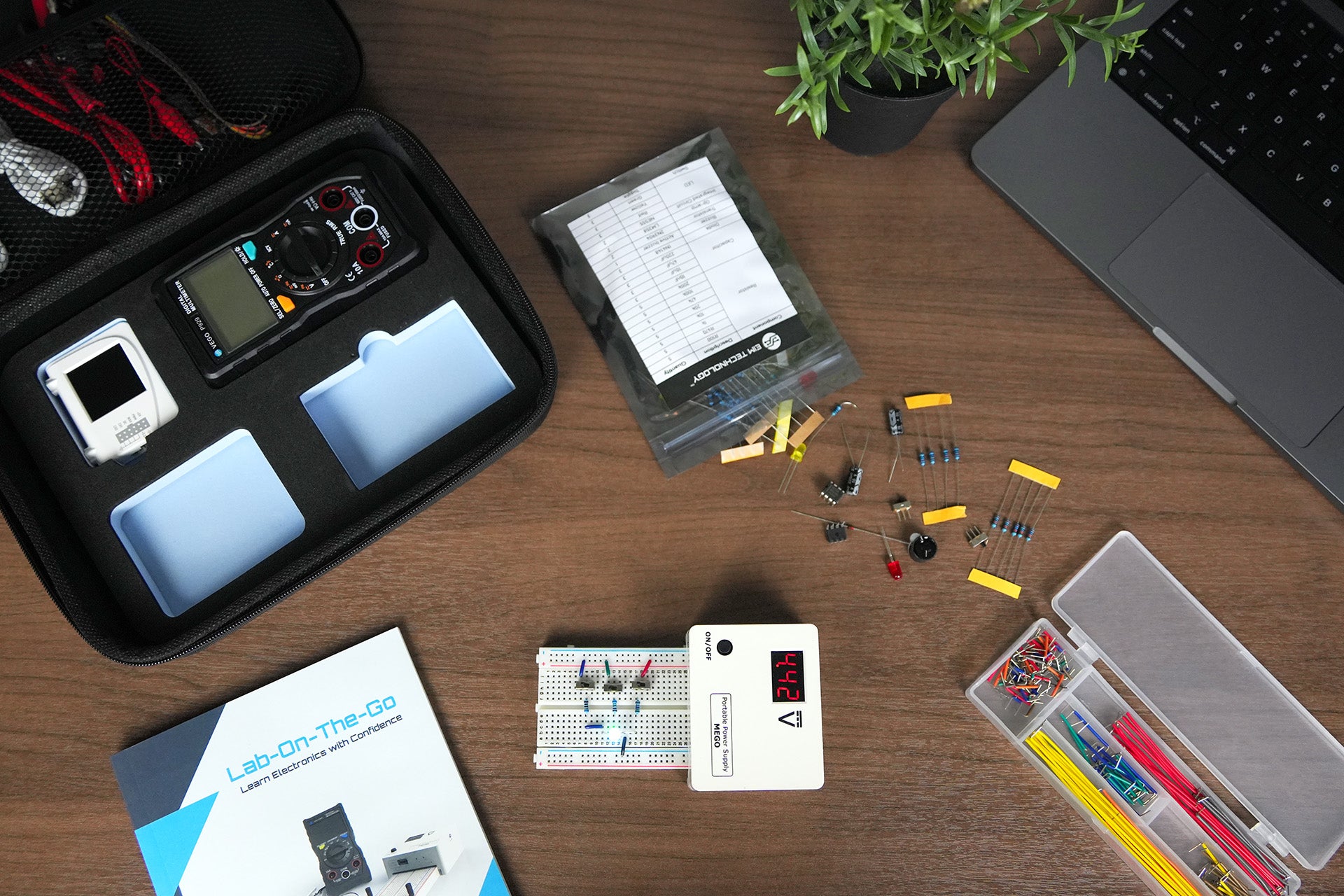
Learn about NE555
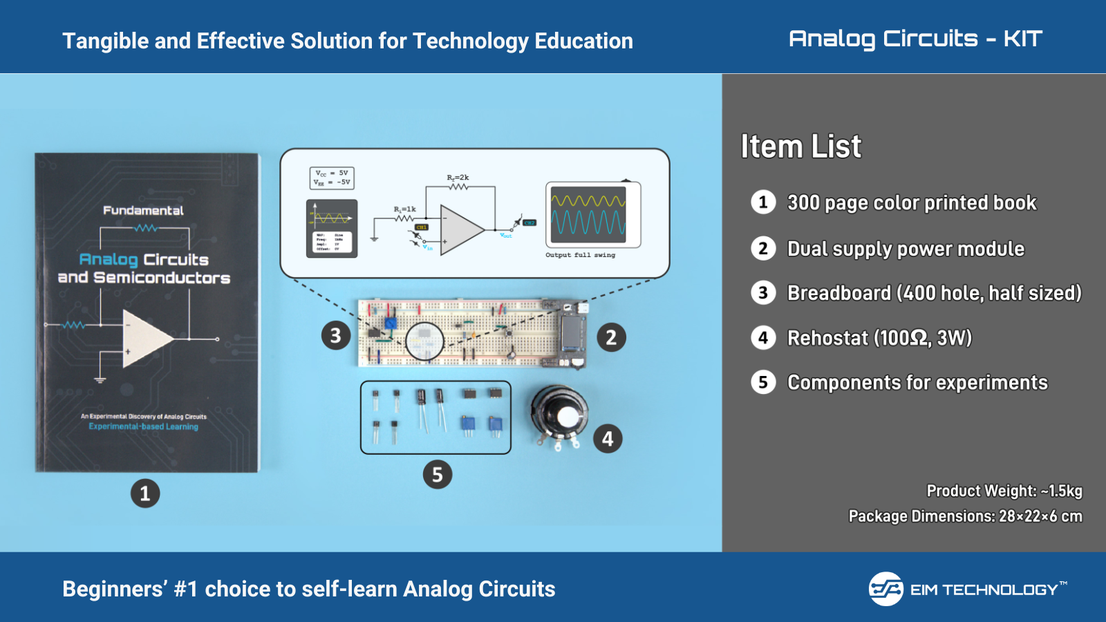
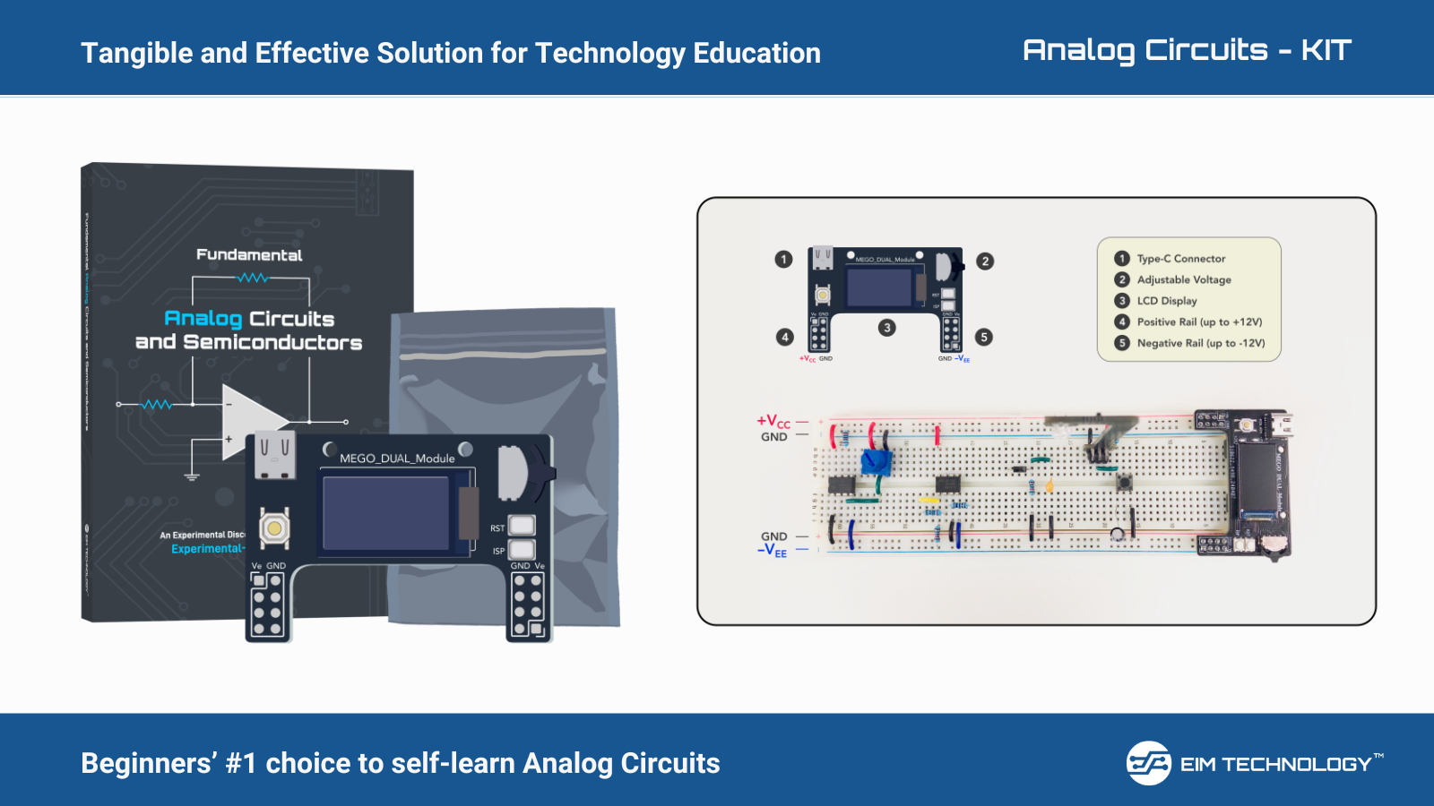
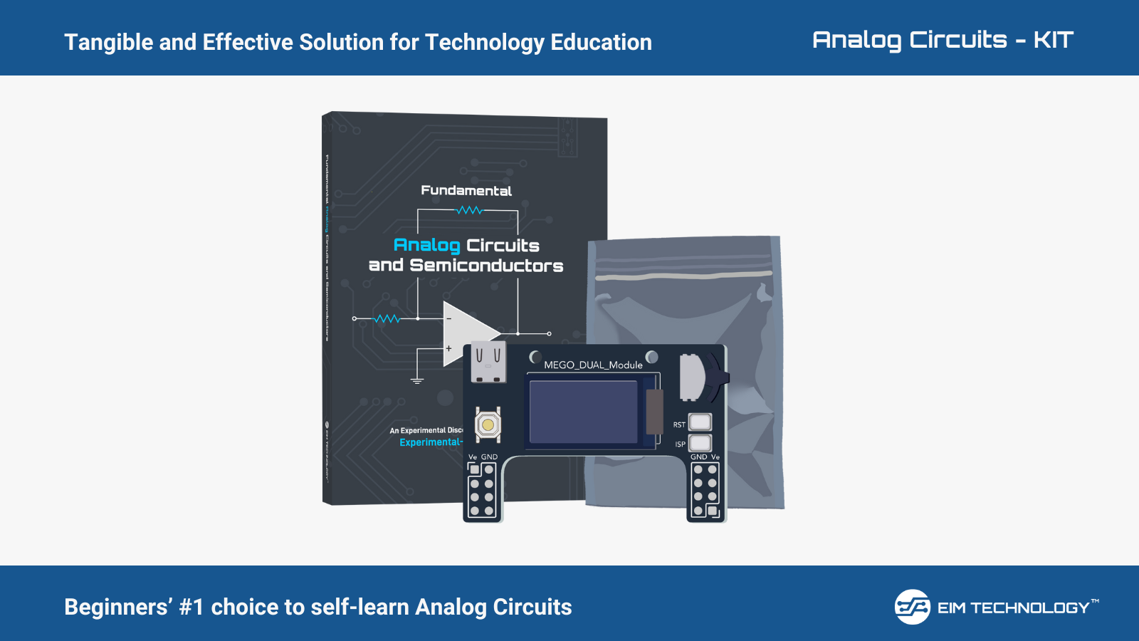
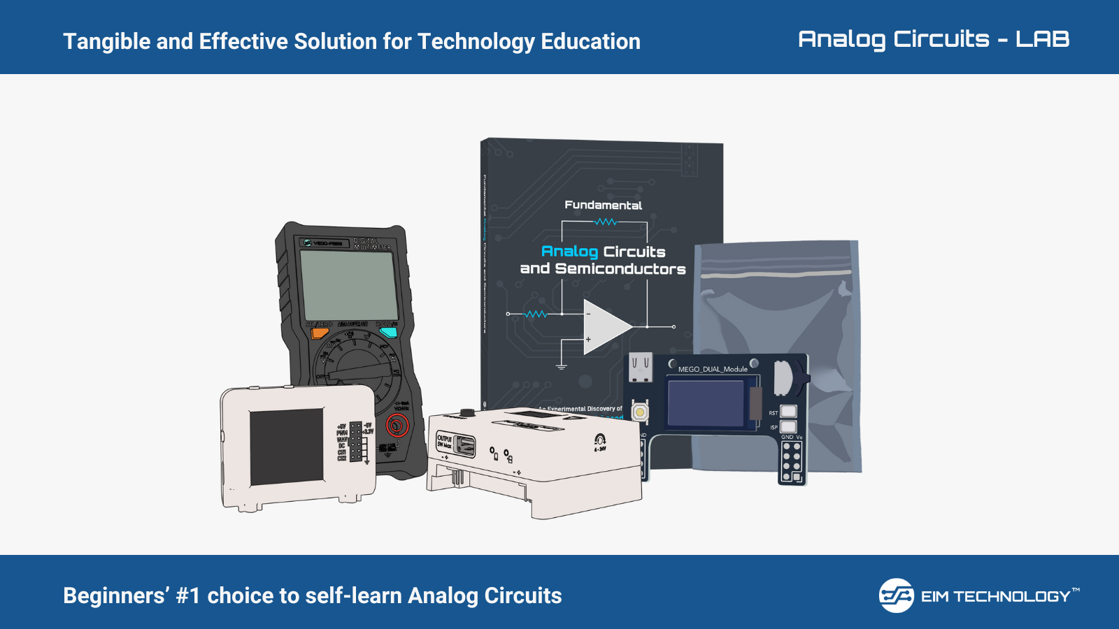
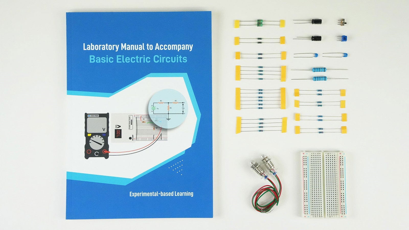
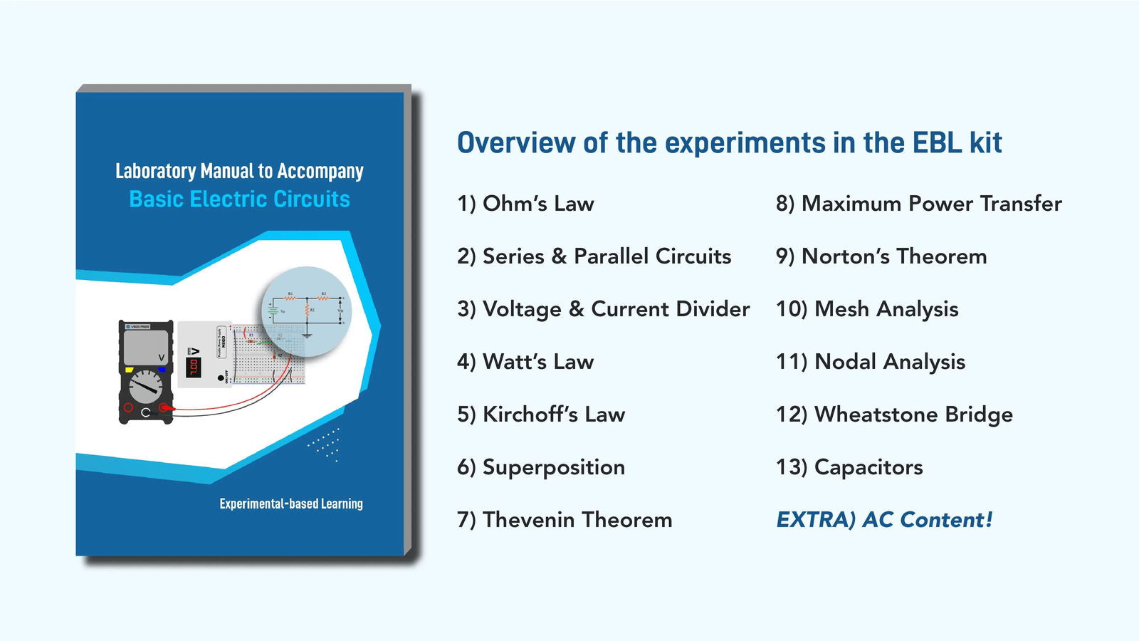
To learn about the 555 timer circuit and create fun experiments using it to get our electronic lab equipment Kit - Lab-On-The-Go
We have explained the Pin Configuration of 555 Timer IC in our blog - https://www.eimtechnology.com/blogs/articles/pin-configuration-of-555-timer
To summarize, the internal structure of the of the 555 Timer Circuit, consisting of the voltage divider, comparators, flip-flop, discharge transistor, output stage, and control pins, allows it to perform a wide range of timing and waveform generation tasks in electronic circuits.