To read a schematic, start by finding power and ground. Then identify each symbol by its label and value, follow the lines between them (a dot means a connection, a plain crossing does not), and read the signal path from input on the left to output on the right. Finally, split the circuit into blocks: power, input, processing, and output.
The reading order: Power and ground → Components → Connections → Signal path → Blocks → Datasheet pins
This guide covers low-voltage electronic schematics for breadboards and circuit boards. House wiring and automotive diagrams share some symbols but follow different conventions, and nothing here prepares you to work on mains wiring. Leave household electrical work to a licensed electrician.
What is a schematic, and how is it different from other circuit drawings?
A schematic shows how components are electrically connected, not where they sit. Two parts drawn side by side may be far apart on the board, because the drawing is arranged for readability.
| Drawing | What it shows | When you use it |
|---|---|---|
| Schematic | Electrical connections between components | Understanding, designing, and debugging a circuit |
| Wiring diagram | Physical wires between devices, often with colours | Installing or repairing equipment |
| Breadboard layout | Where each part and jumper goes on a breadboard | Building a prototype |
| PCB layout | Copper traces and part positions on a board | Manufacturing a circuit board |
What do the most common schematic symbols mean?
North American schematics usually draw a resistor as a zigzag; the IEC style used in many other countries draws a rectangle. Most other symbols are similar in both.
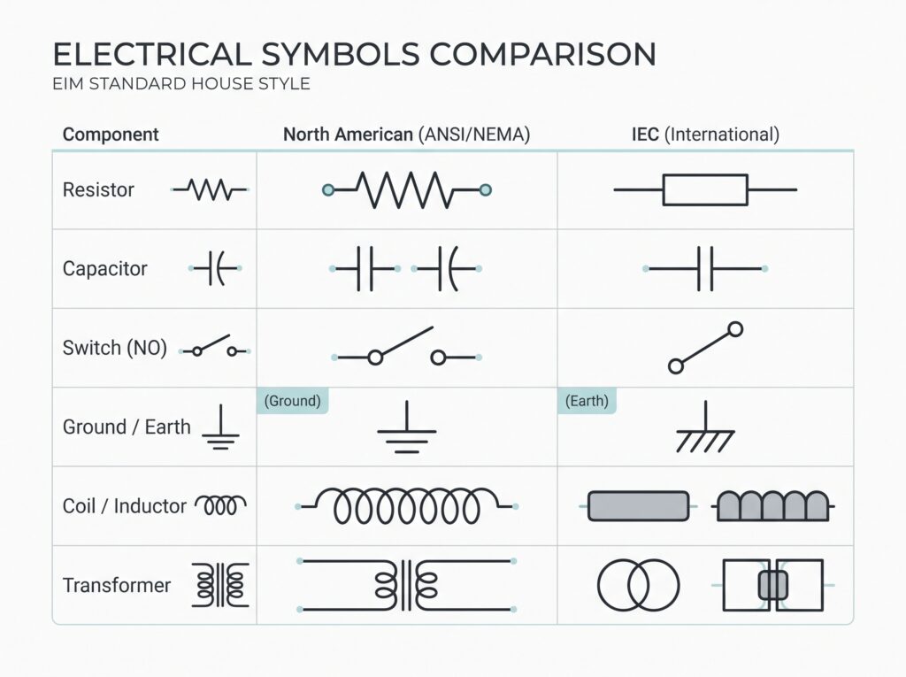
| Symbol | Component | What to look for |
|---|---|---|
| Zigzag line or small rectangle | Resistor | Labelled R1, R2, with a value such as 10k |
| Two parallel lines | Capacitor | One curved line or a + sign means it is polarized |
| Series of loops | Inductor | Labelled L1, L2 |
| Triangle pointing at a bar | Diode | Current flows in the direction of the triangle |
| Diode with two small arrows pointing out | LED | The bar marks the cathode (on the physical LED, usually the shorter leg) |
| Circle with three leads and an arrow | Transistor | On a bipolar transistor the arrow marks the emitter: pointing out for NPN, pointing in for PNP |
| Triangle with two inputs and one output | Op-amp | Inputs marked + and – |
| Rectangle with numbered pins | Integrated circuit (IC) | Labelled U1, U2, with pin numbers |
| Stacked lines of decreasing length, or a downward-pointing triangle | Ground | Ground symbols with the same name are connected, even when no line is drawn |
| Long and short parallel lines | Battery or DC source | The longer line is positive |
How do you read a schematic step by step?
1. Find power and ground
Look for labels such as VCC, 5V, 3V3, or VIN, and for ground symbols or GND labels. Power and ground are often not drawn as continuous lines: every point with the same label is connected.
2. Identify each component
Each part has a reference designator (R for resistor, C for capacitor, D for diode, Q for transistor, U for an IC) and a value. Values often use shorthand: 4k7 means 4.7 kΩ, and 100n means 100 nF. In 4k7, the letter replaces the decimal point so it cannot be lost when the drawing is printed small.
3. Follow the connections
Each line is a wire. A dot where lines meet means they are connected, and a T-junction, where one line ends on another, is a connection too. Lines that cross without a dot are not connected. Careful drafters avoid four-way junctions and draw two offset T-junctions instead, so a faint dot cannot be misread. Labels placed on lines, called net labels, connect every point with the same name.
4. Trace the signal path
Many schematics put inputs on the left, outputs on the right, power at the top, and ground at the bottom. Start at the input and ask what each part does to the signal as it passes.
5. Break the circuit into blocks
Most circuits are a few familiar blocks joined together: a power supply, a sensor or input stage, an amplifier or processor, and an output. You will also see small capacitors placed between power and ground next to each IC. These are decoupling capacitors, and they keep the IC’s supply steady. Once you recognize the blocks, a large schematic becomes several small ones.
6. Check IC pins against the datasheet
On a schematic, IC pins are arranged to make the drawing clear, not in their physical order. Pin 1 may be drawn next to pin 8. Some ICs are split into several symbols: a quad op-amp may appear as U1A, U1B, U1C, and U1D in different places, with its power pins drawn as a separate block. Before you build, check every pin number against the part’s datasheet.
How do you read a real circuit? A worked LED example
Example circuit, in words: a 5 V supply connects to one end of R1 (330 Ω). The other end of R1 connects to the anode of D1, an LED. The cathode of D1 connects to ground.
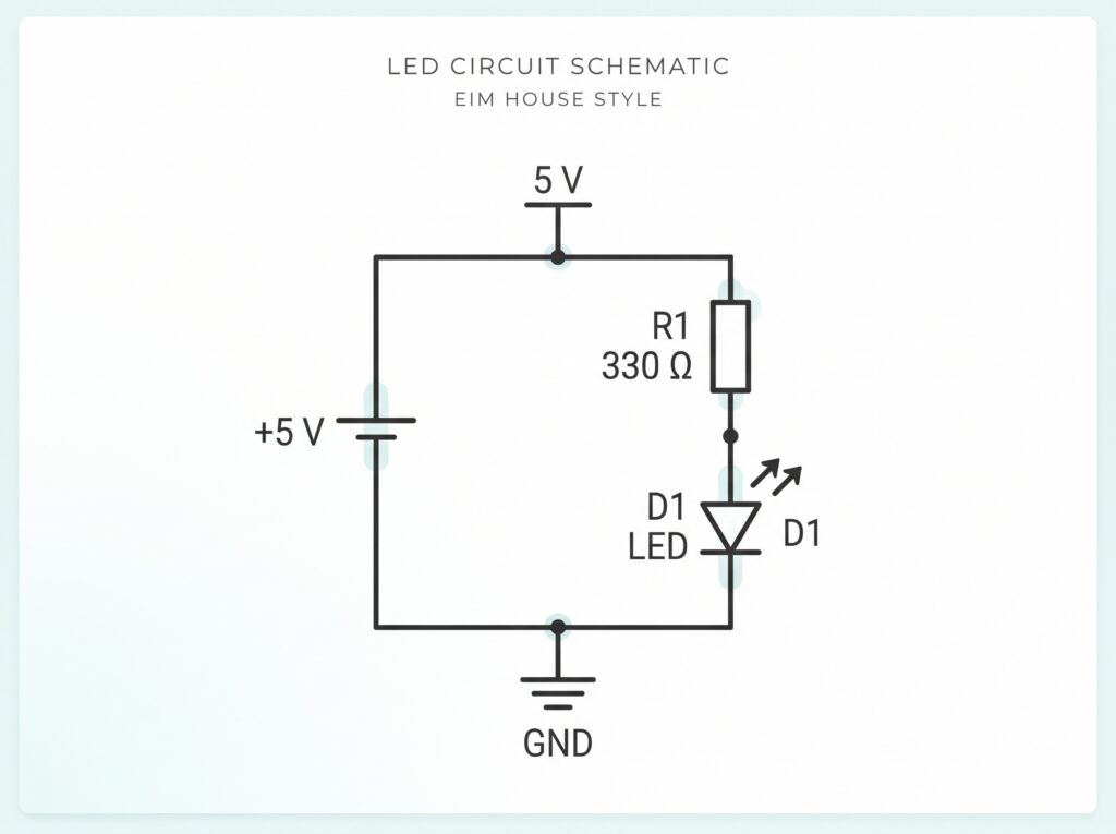
Reading it with the steps above: power is 5 V and ground is GND. R1 and D1 are in series with no junctions, so the same current flows through both, from 5 V, through the resistor that limits it, through the LED, and to ground. One block, one job.
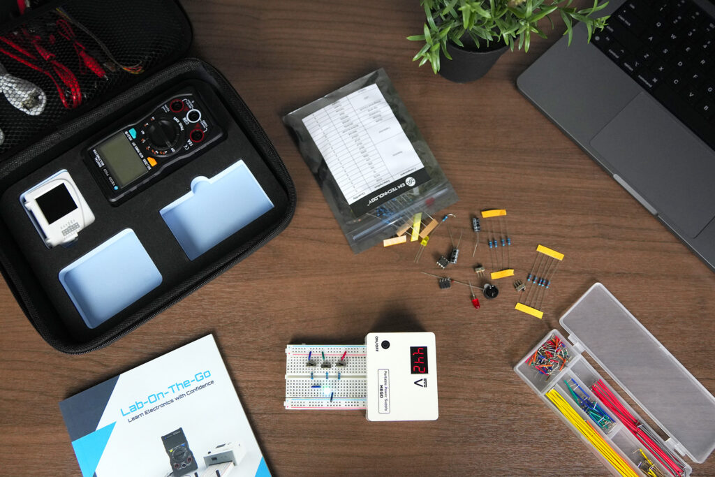
Lab-On-The-Go Electronics Tool Kit
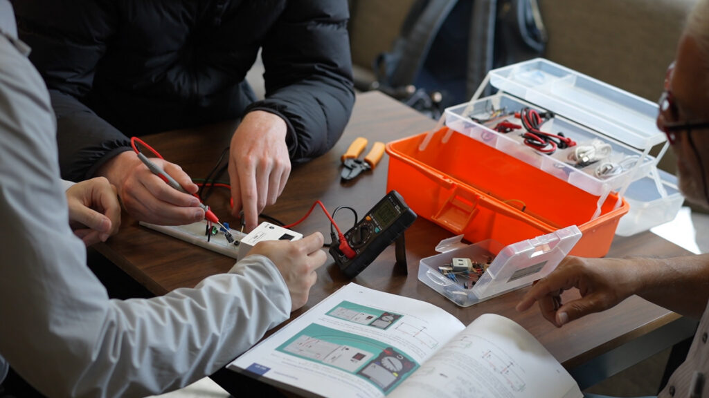
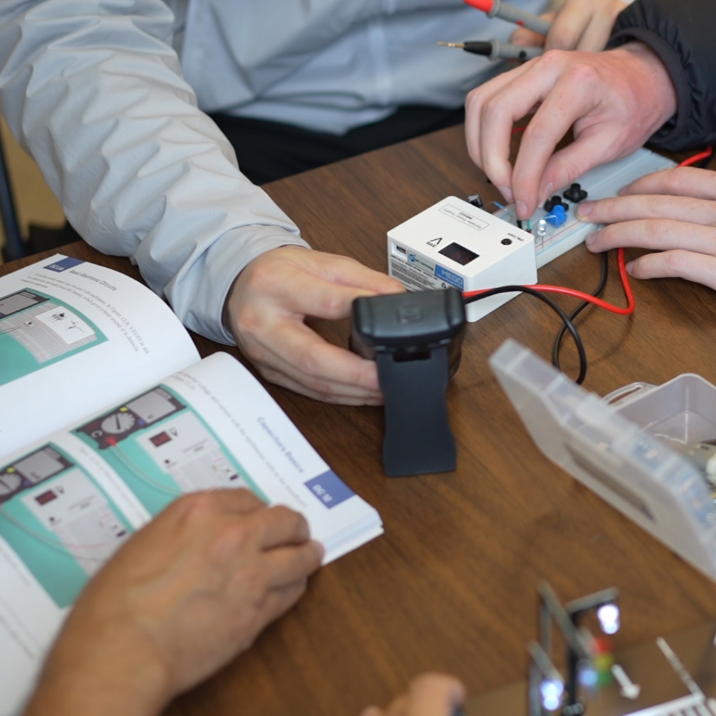
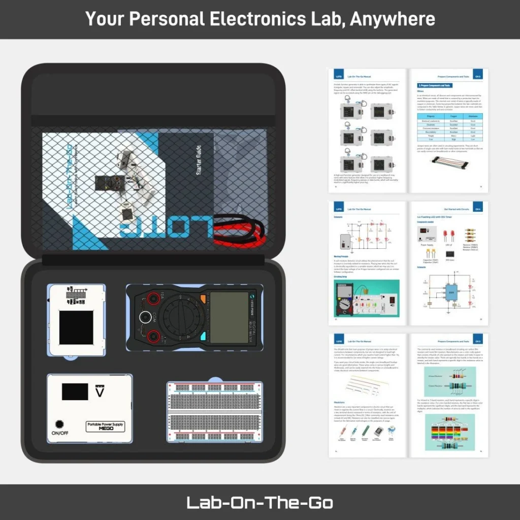
The measuring step is where many learners get stuck, because it depends on instruments that are not always accessible outside a lab. A portable kit such as the Lab-On-The-Go puts a rechargeable power supply, a digital multimeter, and an oscilloscope with a function generator in one case, so a student can capture that unexpected waveform at their own desk and work through the loop at their own pace
How do you turn a schematic into a breadboard circuit?
- Print the schematic or keep it on a second screen.
- Connect the breadboard power rails to your supply, and confirm which rail is positive.
- Place through-hole (DIP) ICs across the centre channel so their two rows of pins are not shorted together. Surface-mount parts need a breakout board first.
- Build one net at a time. A net is every point joined by the same line or label.
- Tick off each connection on the printed schematic as you make it.
- Before applying power, check for shorts between power and ground with a multimeter on continuity mode.
For the equipment that makes this easier, see EIM’s guide on how to build an electronics lab.
What mistakes do beginners make when reading schematics?
- Treating a crossing as a connection. No dot means no connection.
- Missing hidden power connections. ICs often have power pins that are not drawn on every page. Check the datasheet or a separate power section.
- Reading pin positions as physical positions. Always confirm pin numbers against the datasheet.
- Misreading value shorthand. 1k0 is 1 kΩ, and 1M is 1 MΩ, not 1 mΩ.
- Reversing polarized parts. Electrolytic and tantalum capacitors, diodes, and LEDs only work one way round, and a reversed tantalum capacitor can fail violently. Check the + sign or the cathode bar.
Where can you practise reading schematics?
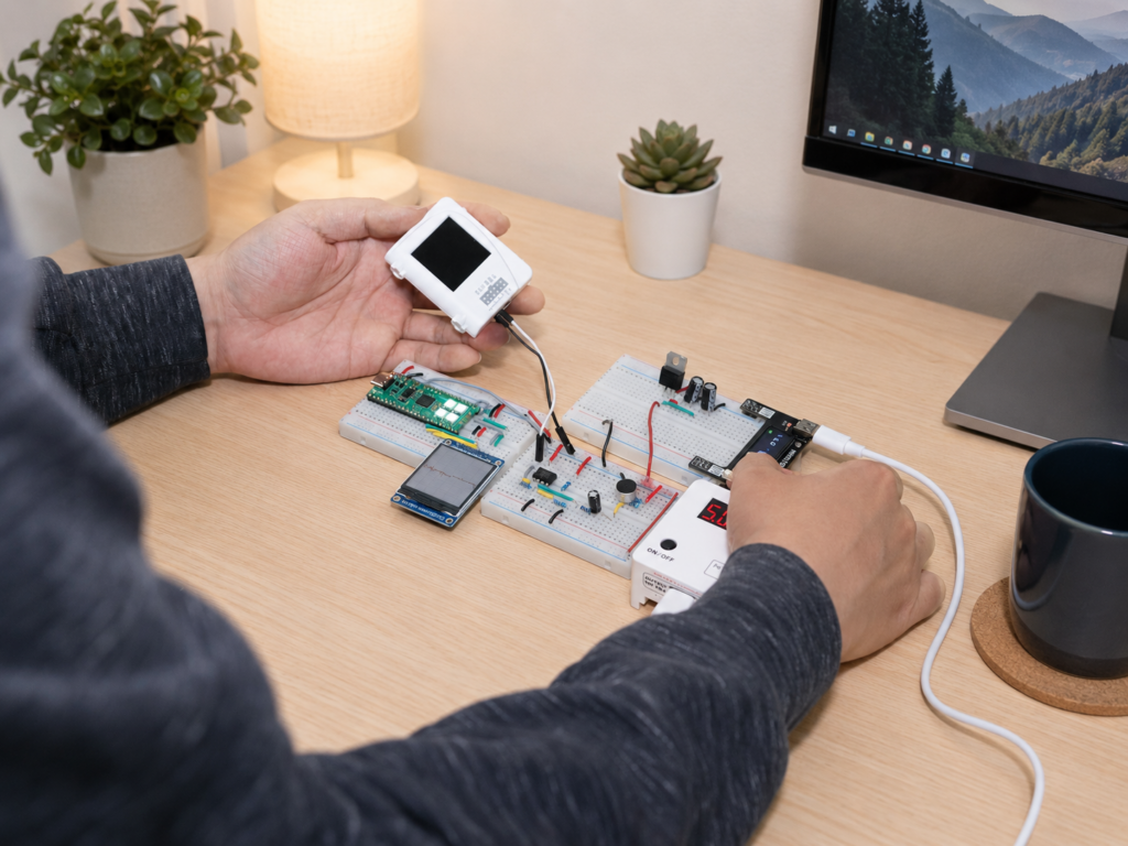
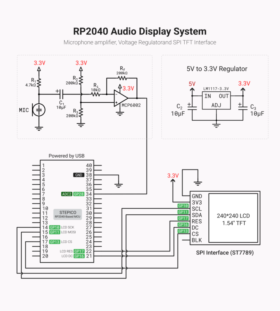
Read a schematic, then build it. Start with an LED and resistor, then a voltage divider, then a circuit with an IC. When you are ready for a full system, try reading the RP2040 audio display system schematic below with the six steps: find power and ground, the RP2040 microcontroller, and the signal path.
For first circuits to try, see EIM’s guides to Ohm’s law experiments and voltage divider experiments.
Disclosure: this article is from EIM Technology, which makes the Fundamental EE Starter (FE11). If you want a structured path, FE11 comes with a printed lab manual and structured online learning materials. It includes through-hole components and ICs for breadboard practice, so you can build circuits from a schematic yourself, plus a fully soldered surface-mount PCB for longer-term projects.
Buy the Fundamental EE Starter (FE11)
For projects to build once you can read schematics, see electrical engineering projects for students. For the wider learning path, see How to Learn Electronics and Computer Engineering.
Frequently asked questions
Do I need to memorize every schematic symbol?
No. The ten symbols in the table above cover most beginner circuits. For anything unfamiliar, check the component’s datasheet or the legend that many schematics include.
Which way does current flow on a schematic?
Conventional current flows from positive to negative, from the power label toward ground. Diode and LED symbols point in the direction of conventional current.
What does a dot mean on a schematic?
A dot marks a junction where lines are connected. Lines that cross without a dot are not connected.
Why are there two different resistor symbols?
They come from two drawing standards. The zigzag is common in North America, and the rectangle is the IEC style used widely elsewhere. Both mean the same component.

EIM TECHNOLOGY
Founder & Engineering Education Innovator
Daniel Cao is the Founder of EIM Technology and holds a Master of Applied Science in Engineering. With experience in engineering research, product development, PCB design, and technical education, he is the author of several books on electronics engineering. His work focuses on developing practical learning systems that integrate engineering hardware, lab instruments, curriculum, and project-based learning. Through EIM Technology, Daniel aims to make electronics and computer engineering more accessible and engaging, helping students build real experience in designing, measuring, testing, and troubleshooting electronic systems.